
Stereoscopic image display control apparatus, and method and program for controlling operation of same

a control apparatus and stereoscopic image technology, applied in the field of stereoscopic image display control apparatus and to a method and program for controlling the operation of this apparatus, can solve problems such as problems, and achieve the effect of eliminating margins

Inactive Publication Date: 2012-03-08
FUJIFILM CORP
View PDF5 Cites 1 Cited by
  • Summary
  • Abstract
  • Description
  • Claims
  • Application Information

AI Technical Summary

Benefits of technology

[0006]An object of the present invention is to so arrange it that a margins can be eliminated from an image compositing area when a stereoscopic image is displayed in the image compositing area.
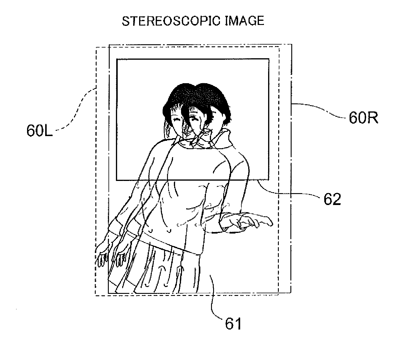
[0010]In accordance with the present invention, a superimposed image portion, which is obtained by superimposing a left-eye image and a right-eye image that constitute a stereoscopic image, is displayed in an image compositing area. When a parallax-amount enlargement command is applied, this enlarges the amount of parallax, which is the amount of horizontal offset between the left- and right-eye images. If the amount of parallax is enlarged, the width of the superimposed image portion in the horizontal direction decreases. Enlarging the amount of parallax, therefore, causes margins to be produced in the image compositing area. In the present invention, whether margins will be produced in the image compositing area by enlargement of the amount of parallax is determined. If it is determined that margins will be produced, then the processing that enlarges the amount of parallax is nullified. This makes it possible to prevent margins from being formed in the image compositing area.

Problems solved by technology

In cases where an image compositing area has been defined, however, problems can arise when a stereoscopic image is pasted in such an image compositing area.

Method used


Image

  • Stereoscopic image display control apparatus, and method and program for controlling operation of same
  • Stereoscopic image display control apparatus, and method and program for controlling operation of same
  • Stereoscopic image display control apparatus, and method and program for controlling operation of same

Examples


Embodiment Construction

[0029]Preferred embodiments of the present invention will be described in detail with reference to the drawings.

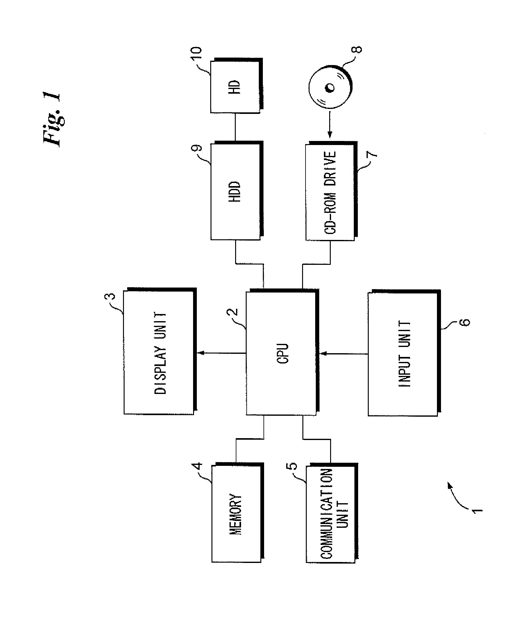
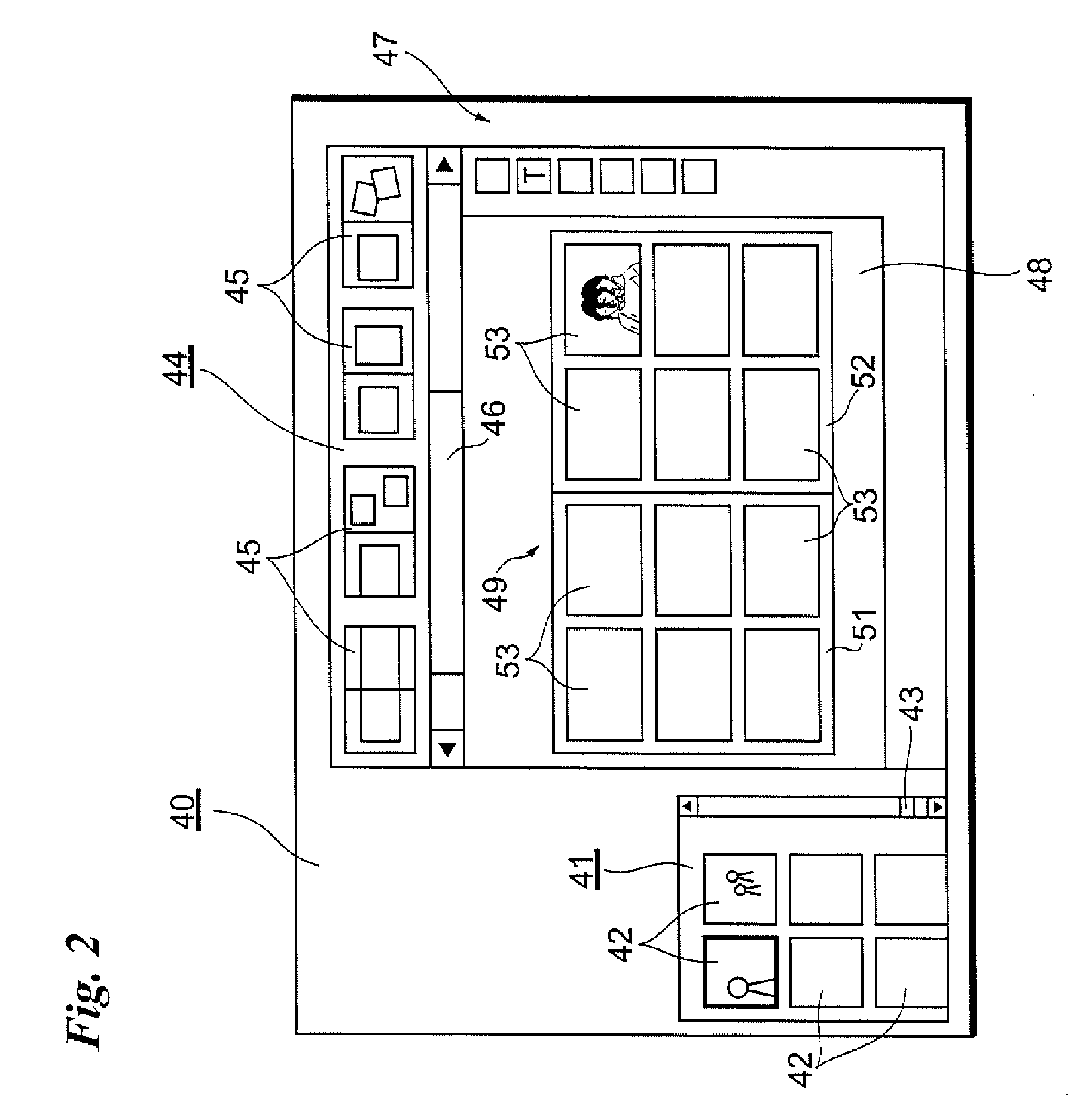
[0030]FIG. 1 is a block diagram illustrating the electrical configuration of a personal computer 1 according to an embodiment of the present invention. In this embodiment, the personal computer 1 communicates with a server computer (not shown) via the Internet. While communicating with the server computer, the user creates an electronic album using the personal computer 1. Naturally, the user may generate an electronic album without communicating with the server computer and is also capable of generating an electronic album utilizing a store terminal, which has been installed at a supermarket or convenience store, etc., without using the personal computer 1. In this case, the store terminal would have the electrical configuration shown in FIG. 1.

[0031]The overall operation of the personal computer 1 is controlled by a CPU 2.

[0032]The personal computer 1 includes a display ...


PUM


Abstract

A parallax adjusting command is applied when a stereoscopic image is displayed in an image compositing area defined on a page constituting an electronic album. The amount of parallax is enlarged in response to application of a command for enlarging the amount of parallax. If enlarging the amount of parallax results in margins being produced when the stereoscopic image is displayed in the image compositing area, the enlargement of the amount of parallax is not reflected in the display of the stereoscopic image. Thus, margins are prevented from being produced in the image compositing area.

Description

BACKGROUND OF THE INVENTION[0001]1. Field of the Invention[0002]This invention relates to a stereoscopic image display control apparatus and to a method and program for controlling the operation of this apparatus.[0003]2. Description of the Related Art[0004]There is a technique for eliminating a gap between an image and a photo frame when an image is pasted in the photo frame of an electronic album (see Japanese Patent Application Laid-Open No. 2006-134230). Further, since the amount of stereoscopic pop-up (depth perception) of a stereoscopic image is not uniquely decided when a stereoscopic image is displayed, there are techniques for adjusting the amount of pop-up (see Japanese Patent Application Laid-Open Nos. 2010-45584 and 8-205203). Since the amount of pop-up varies depending upon enlargement and reduction of image size, there is a technique for determining whether a changed amount of pop-up falls within parallax limits (see Japanese Patent No. 4259913).[0005]In cases where an...

Claims


Application Information

Patent Timeline
IPC IPC(8): G06T15/00
CPCH04N13/0022H04N13/128
Inventor YAMAJI, KEI
Owner FUJIFILM CORP
Learn More