
Laser light source apparatus

a technology of laser light source and concave mirror, which is applied in the direction of lighting and heating apparatus, semiconductor lasers, instruments, etc., can solve the problems of difficulty in adjustment and distinctiveness, and achieve the effect of reducing the need for optical axis adjustment, facilitating optical axis adjustment, and simple and easy determination of the position of the concave mirror

Inactive Publication Date: 2012-12-27
PANASONIC CORP
View PDF4 Cites 2 Cited by
  • Summary
  • Abstract
  • Description
  • Claims
  • Application Information

AI Technical Summary

Benefits of technology

"The present invention provides a laser light source apparatus that can maintain a stable laser output and adjust the optical axis of other optical elements with a high degree of precision. This is achieved by using a semiconductor laser, a laser medium, a wavelength conversion element, a concave mirror, and a concave mirror supporter. The concave mirror supporter has a mouth that transmits laser light from the wavelength conversion element and a contacting surface that intersects with the optical axis of the laser light. This allows for easy positioning and adjustment of the concave mirror, which in turn helps to maintain the optimal laser output and optical axis alignment."

Problems solved by technology

In the above-mentioned conventional technology, however, due to a manufacturing error in the concave mirror, simply determining a position of the concave mirror does not necessarily match the center of the concave surface with the optical path of the laser light.
Thus, a circumstance arises in which there is not enough margin (range within which an optical axis of laser light can be displaced by changing a position and tilt of each optical element) for adjustment of an optical axis of laser light including other optical elements in the laser light source apparatus, causing difficulty in the adjustment.
In particular, when a concave mirror of a small size (an outer diameter is 0.5 mm, for example) is employed, such a difficulty becomes distinctive.

Method used


Image

  • Laser light source apparatus
  • Laser light source apparatus
  • Laser light source apparatus

Examples


Embodiment Construction

[0028]The particulars shown herein are by way of example and for purposes of illustrative discussion of the embodiments of the present invention only and are presented in the cause of providing what is believed to be the most useful and readily understood description of the principles and conceptual aspects of the present invention. In this regard, no attempt is made to show structural details of the present invention in more detail than is necessary for the fundamental understanding of the present invention, the description is taken with the drawings making apparent to those skilled in the art how the forms of the present invention may be embodied in practice.

[0029]Hereinafter, an embodiment of the present invention will be explained with reference to the drawings.

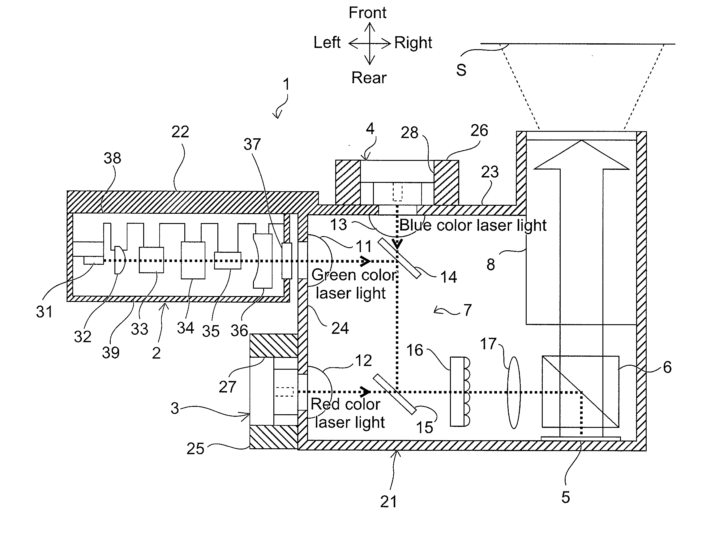
[0030]FIG. 1 schematically illustrates a configuration of an image display apparatus 1 according to the present invention. The image display apparatus 1 projects a predetermined image to display on a screen, and is config...


PUM


Abstract

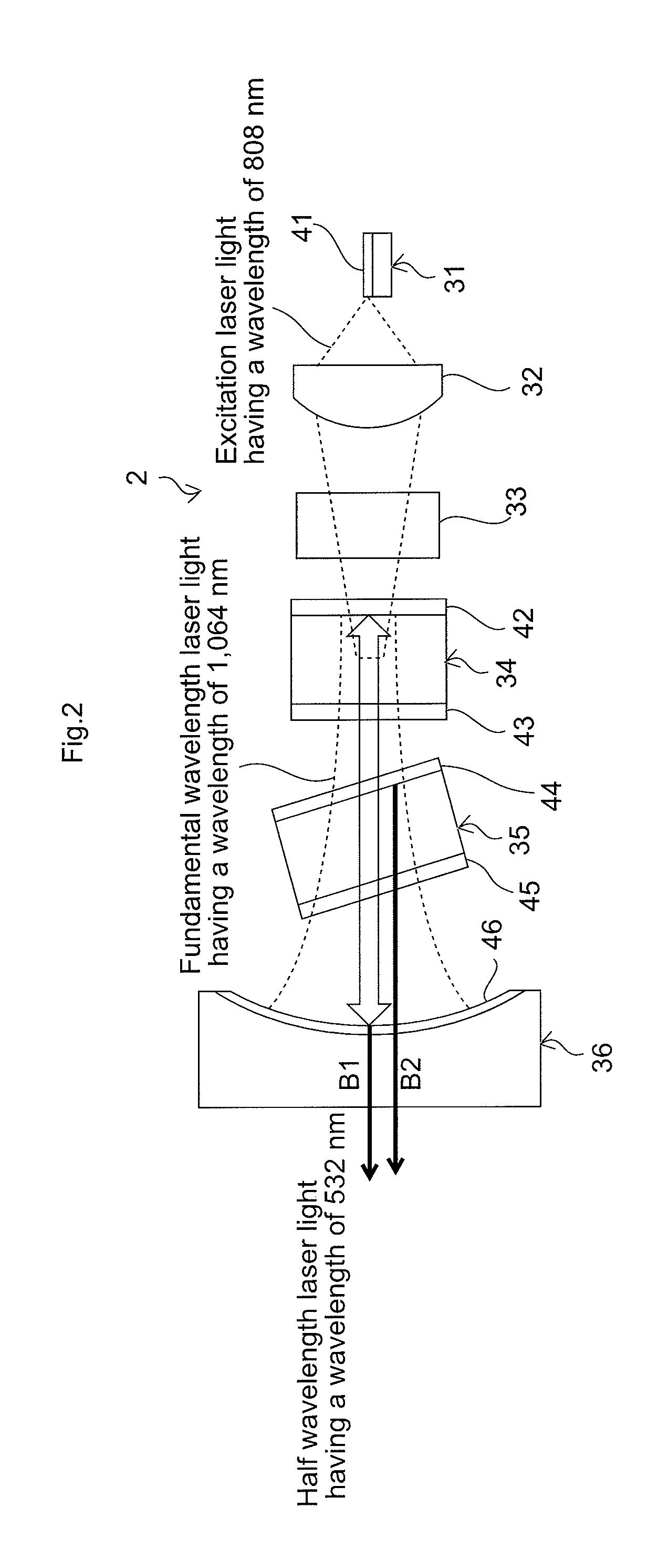
Provided is a laser light source apparatus capable of maintaining a favorable level of laser output and inhibiting a margin for optical axis adjustment required for other optical elements. The present invention includes: a semiconductor laser emitting excitation laser light; a laser medium excited by the excitation laser light and emitting infrared laser light; a wavelength conversion element converting a wavelength of the infrared laser light and emitting harmonic laser light; a concave mirror having a concave surface opposing the conversion element; and a mirror supporter supporting the concave mirror. The mirror supporter has a mouth that transmits laser light from the conversion element toward the concave mirror, and a contacting surface orthogonally intersecting an optical axis of the laser light from the conversion element and contacting the concave surface side of the concave mirror.

Description

CROSS-REFERENCE TO RELATED APPLICATIONS[0001]The present application claims priority under 15 U.S.C. §119 of Japanese Application No. 2011-142110, filed on Jun. 27, 2011, the disclosure of which is expressly incorporated by reference herein in its entirety.BACKGROUND OF THE INVENTION[0002]1. Field of the Invention[0003]The present invention relates to a laser light source apparatus. The present invention especially relates to a laser light source apparatus employed as a light source of an image display apparatus.[0004]2. Description of Related Art[0005]In recent years, technology employing a semiconductor laser as a light source of an image display apparatus has drawn attention. Compared with a mercury lamp conventionally used for an image display apparatus, the semiconductor laser has various advantages including good color reproducibility, instant light-up, long life, high efficiency reducing power consumption, easy miniaturization, and the like.[0006]The laser light source appara...

Claims


Application Information

Patent Timeline
Patent Type & Authority Applications(United States)
IPC IPC(8): G03B21/14F21V9/16
CPCH01S3/09415H01S3/109H01S3/1611H01S3/1673H01S3/2391G02F2001/3542H01S3/025H04N9/3111H04N9/3161G02F1/37G02F2001/3503H01S5/02252G02F1/3503G02F1/3542H01S5/02326
Inventor HATASE, YUICHIMATSUO, TOMOHIRONAKAYAMA, KENJISUYAMA, KOHEI
Owner PANASONIC CORP
Learn More