
Magnetic resonance type isolator

a type of isolator and magnetic resonance technology, applied in waveguide type devices, basic electric elements, electrical apparatus, etc., can solve the problems of incompatibility, increasing the density of the components of the communication device, and increasing the density of the communication device. , to achieve the effect of reducing the siz

Active Publication Date: 2012-03-08
MURATA MFG CO LTD
View PDF0 Cites 4 Cited by
  • Summary
  • Abstract
  • Description
  • Claims
  • Application Information

AI Technical Summary

Benefits of technology

The present invention provides a magnetic resonance type isolator that is small in size and can adjust input and output impedances. It includes a ferrite with a connection conductor and a permanent magnet that applies a direct current magnetic field to the ferrite. A main line and an end portion of a sub-line do not resonate, and a first reactance element is connected to the third port. A second reactance element is connected between the first and second ports. The magnetic resonance type isolator can be used in a compact and low-impedance configuration. It can also improve insertion loss and reduce leakage of magnetic flux. The ferrite can be sandwiched between a pair of permanent magnets and mounted on a mounting substrate. Overall, the magnetic resonance type isolator provides a solution for reducing size and adjusting impedance in a compact and efficient manner.

Problems solved by technology

This is not compatible with the current situation in which mobile communication devices have been becoming increasingly smaller in recent years and the density with which components thereof are mounted has been becoming increasingly high.
Furthermore, it is necessary to adjust the impedances of the input and output, but magnetic resonance type isolators of the related art have been unable to satisfy this requirement and it has been necessary to provide such isolators with a separate impedance conversion device as a separate component.

Method used


Image

  • Magnetic resonance type isolator
  • Magnetic resonance type isolator
  • Magnetic resonance type isolator

Examples


first preferred embodiment

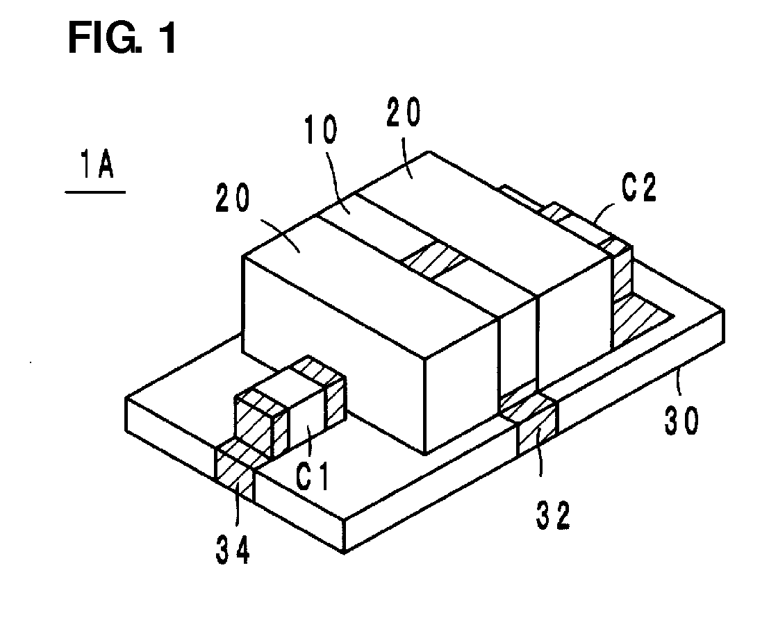
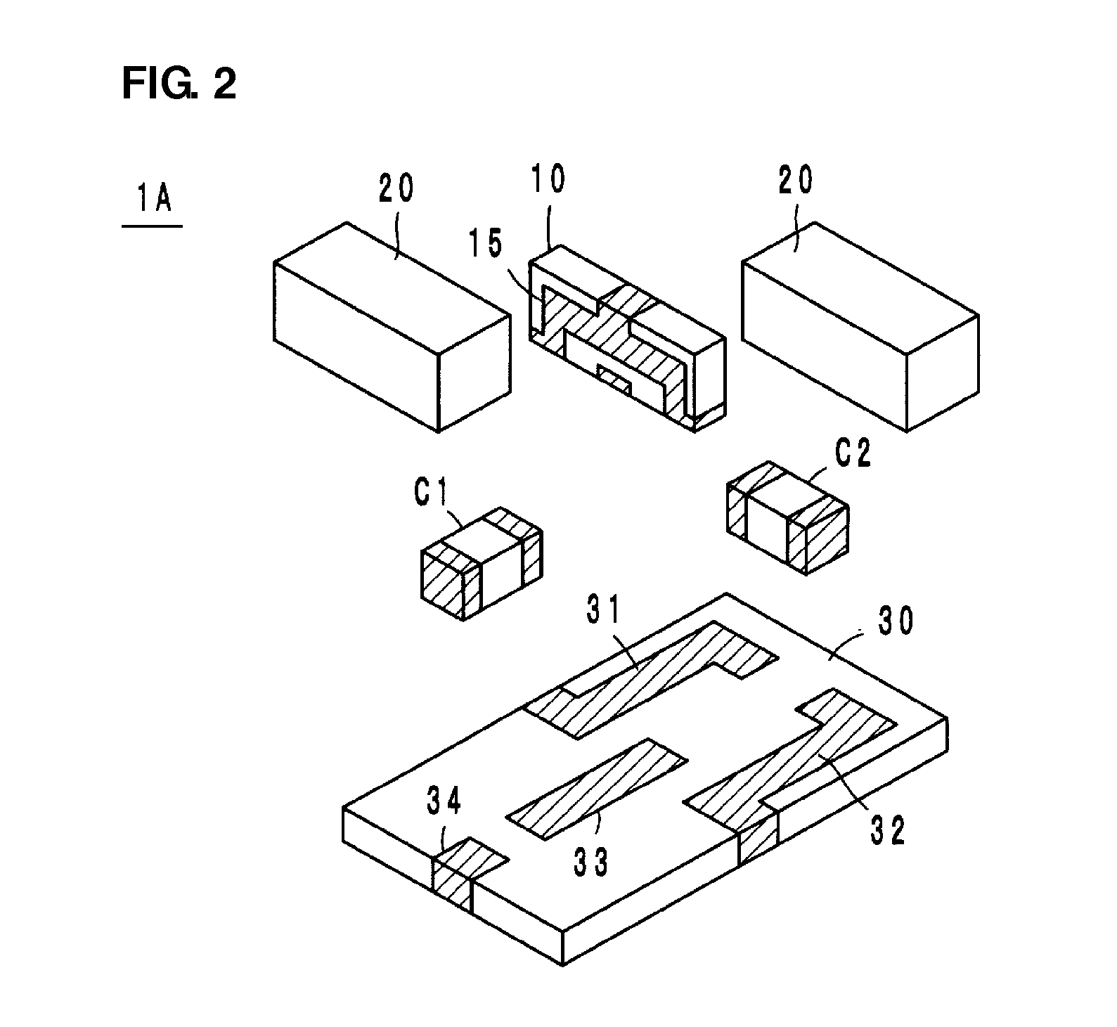
[0033]A magnetic resonance type isolator 1A according to a first preferred embodiment will be described hereafter with reference to FIGS. 1 to 5D.

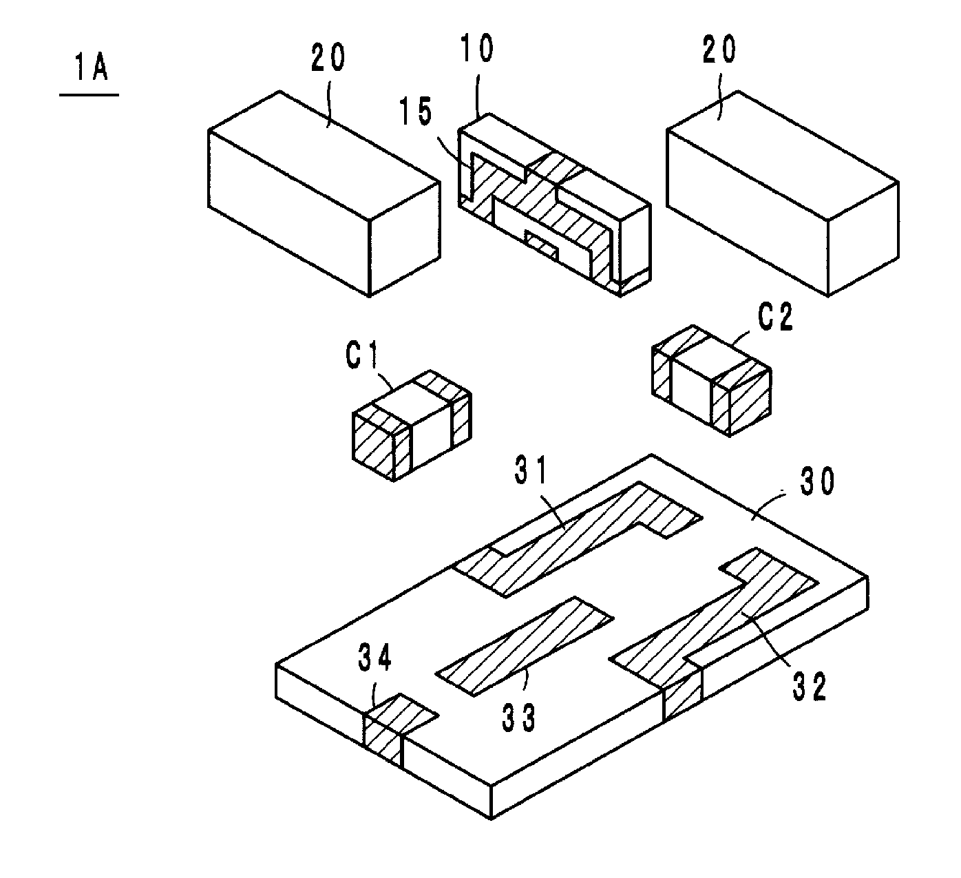
[0034]As illustrated in FIGS. 1 and 2, the magnetic resonance type isolator 1A according to the first preferred embodiment includes a ferrite 10, a connection conductor 15 including three ports P1, P2 and P3 and arranged on a first main surface 11 of the ferrite 10, a pair of permanent magnets 20 that apply a direct current magnetic field to the ferrite 10, a capacitor C1 that defines a first reactance element, a capacitor C2 that defines a second reactance element, and a mounting substrate 30.

[0035]The connection conductor 15 preferably is a thin film formed by, for example, deposition of a conductive metal or is a thick film formed by applying and baking a conductive paste. As illustrated in FIGS. 3A and 3B, a main line, which is arranged between the first port P1 and the second port P2 that face each other along a straight line, among t...

second preferred embodiment

[0044]A magnetic resonance type isolator 1B according to a second preferred embodiment will be described hereafter with reference to FIGS. 6 and 7A to 7D.

[0045]The magnetic resonance type isolator 1B according to the second preferred embodiment preferably has the same configuration as that of the first preferred embodiment except that an inductor L1 is preferably used as the second reactance element.

[0046]The operational advantages of the second preferred embodiment are basically the same as those of the first preferred embodiment. The input return loss, isolation, insertion loss and output return loss of the magnetic resonance type isolator 1B according to the second preferred embodiment are illustrated in FIGS. 7A, 7B, 7C and 7D, respectively. The inductance of the inductor L1 preferably is about 5.1 nH and the capacitance of the capacitor C1 preferably is about 3.5 pF, for example. The impedance of the input and output ports preferably is about 10Ω and the electrical characterist...

third preferred embodiment

[0047]A magnetic resonance type isolator 1C according to a third preferred embodiment will be described hereafter with reference to FIGS. 8 to 11D.

[0048]In the magnetic resonance type isolator 1C according to the third preferred embodiment, as illustrated in the equivalent circuit of FIG. 10, an inductor L2 is preferably used as the first reactance element, the capacitor C2 is preferably used as the second reactance element, and capacitors C3 and C4, which are connected to the ground, are respectively connected to the input terminal electrode 31 (first port P1) and the output terminal electrode 32 (second port P2). As illustrated in FIG. 9, the input terminal electrode 31, the output terminal electrode 32, the relay terminal electrode 33 and the ground terminal electrode 34 are provided on the mounting substrate 30. The rest of the configuration is preferably the same as that of the first preferred embodiment.

[0049]One end of the main line (first port P1) is connected to the input t...


PUM


Abstract

A magnetic resonance type isolator includes a ferrite; a connection conductor that is arranged on the ferrite and includes first, second and third ports; a permanent magnet that applies a direct current magnetic field to the ferrite; a capacitor (or an inductor) that defines a first reactance element; and a capacitor (or an inductor) that defines a second reactance element. A main line arranged between the first port and the second port of the connection conductor does not resonate, an end portion of a sub-line that branches off from the main line serves as the third port, and a wave reflected from the sub-line is modulated so that its phase is shifted by 90° or about 90° at an intersection of the connection conductor. One of the capacitors is connected to the third port and the other capacitor is connected between the first port and the second port.

Description

BACKGROUND OF THE INVENTION[0001]1. Field of the Invention[0002]The present invention relates to magnetic resonance type isolators and in particular, relates to magnetic resonance type isolators that are, for example, used in a microwave frequency band.[0003]2. Description of the Related Art[0004]Typically, isolators have a characteristic of only transmitting signals in a specific direction and not transmitting signals in the opposite direction. Isolators are included in transmission circuit units of mobile communication devices such as cellular phones. Known examples of magnetic resonance type isolators include those described in Japanese Unexamined Patent Application Publication Nos. 63-260201 and 2001-326504. Magnetic resonance type isolators utilize a phenomenon that occurs as follows. When high-frequency currents that have the same amplitude but differ in phase by about ¼ of a wavelength flow through two orthogonal lines (having four ports), a magnetic field (circularly polariz...

Claims


Application Information

Patent Timeline
Patent Type & Authority Applications(United States)
IPC IPC(8): H01P1/36
CPCH01P1/387H01P1/365
Inventor HASEGAWA, TAKASHI
Owner MURATA MFG CO LTD
Learn More