
Power-supply control device

Active Publication Date: 2012-03-08
ORMON CORP
View PDF0 Cites 58 Cited by
  • Summary
  • Abstract
  • Description
  • Claims
  • Application Information

AI Technical Summary

Benefits of technology

[0014]A power-supply control device according to one or more embodiments of the present invention prevents breakdown of each load due to abnormalities of a high-voltage battery in starting supply of power from the high-voltage battery to each load.
[0017]Accordingly, before the supply of the power from the battery to each load is started, confirmation that the abnormality of the battery is not generated can be made before supplying the power to each load. As a result, a breakdown of the load caused by the abnormality of the battery can be prevented in starting the supply of the power from the battery.
[0021]Therefore, the variation in charge amount of the battery cell can be decreased.
[0027]Therefore, the cells of the battery can equally be used to further decrease the variation in charge amount of each cell.
[0031]According to one or more embodiments of the present invention, before the supply of the power from the battery to each load is started, the confirmation that the abnormality of the battery is not generated can be made before starting the supply of the power to each load. As a result, the breakdown of the load caused by the abnormality of the battery can be prevented at the start of the supply of the power from the battery.

Problems solved by technology

When a remaining amount of the low-voltage battery becomes a predetermined value or less because the electric-powered vehicle is left for a long time, that is, when so-called battery run-out has occurred, a control system of the electric-powered vehicle cannot be operated irrespective of the remaining amount of the high-voltage battery, and therefore the electric-powered vehicle cannot be started.
In starting the supply of the power from the high-voltage battery to each load, when abnormalities are generated in the high-voltage battery, a voltage equal to or more than a rated voltage may be applied to each load including the DC-DC converter, thereby causing breakdown.

Method used


Image

  • Power-supply control device
  • Power-supply control device
  • Power-supply control device

Examples


first embodiment

Modification of First Embodiment

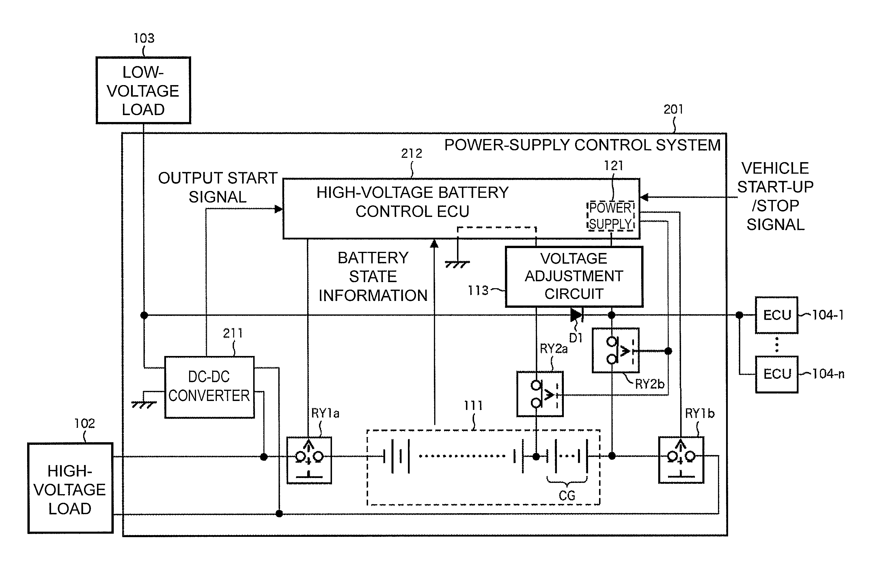
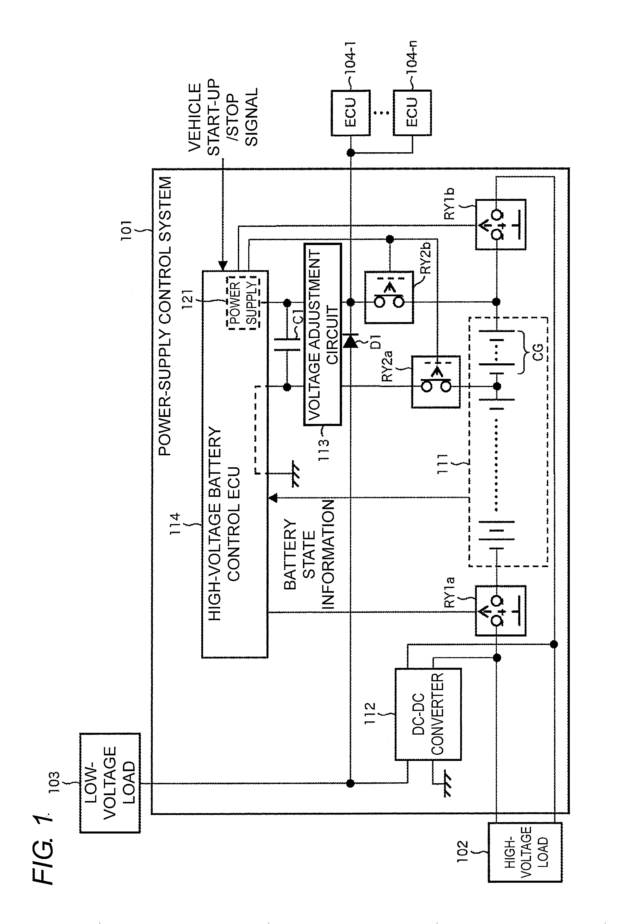
[0107]The capacitor C1 desirably has a capacity that can stably supply the power to the high-voltage battery control ECU 114 and the ECU 104 while the supply source of the power to the high-voltage battery control ECU 114 and the ECU 104 changes from the cell group CG of the high-voltage battery 111 to the DC-DC converter 112 or while the supply source changes from the DC-DC converter 112 to the cell group CG. However, when the capacitor C1 has the capacity that can stably supply the power to at least the high-voltage battery control ECU 114, the high-voltage line can reliably be established by continuing the operation of the high-voltage battery control ECU 114 even if the power of the ECU 104 is turned off to turn off the vehicle start-up signal.

[0108]A capacitor unit similar to that of the capacitor C1 may be provided in the ECU 104.

[0109]Since only the cell group CG in the cells of the high-voltage battery 111 is always used and discharged, desira...

second embodiment

Modification of Second Embodiment

[0141]The power-supply stop processing may be performed according to the flowchart of FIG. 4. In such a case, after the relays RY1a and RY1b are opened, the relays RY2a and RY2b may automatically be closed by turning off the power of the high-voltage battery control ECU 212.

3. Third Embodiment

[0142]A third embodiment of the present invention will be described with reference to FIGS. 9 to 11.

[0143]In the first and second embodiments, in the cells of the high-voltage battery 111, the cell group CG fixedly supplies the power to each ECU (high-voltage battery control ECU 114, high-voltage battery control ECU 212 and ECU 104) by way of example. Therefore, degradation progresses earlier only in the cell group CG, a variation in charge amount is generated in the cells of the high-voltage battery 111, and performance is possibly degraded in the whole of the high-voltage battery 111.

[0144]According to one or more embodiments of the present invention, the appl...

third embodiment

Modification of Third Embodiment

[0178]The selected cell group CG may be stored in the high-voltage battery control ECU 311 or the nonvolatile memory in order to decrease the variation of the cell group CG to be used. For example, when the same cell group CG is continuously selected a predetermined number of times (for example, three times), the cell group CG having the second largest charge amount may be selected next even if the continuously selected cell group CG still has the largest charge amount.

[0179]In the third embodiment, the high-voltage battery control ECU 311 controls the switches SW11 to SW22 by way of example. Alternatively, another ECU may control the switches SW11 to SW22.

[0180]For example, a transistor or a relay may be used as the switches SW11 to SW22. A three-state switch that is an open contact may be used as the switches SW21 and SW22, and the relays RY2a and RY2b may be eliminated.

[0181]The cell group CG used may automatically be rotated irrespective of the ch...


PUM


Abstract

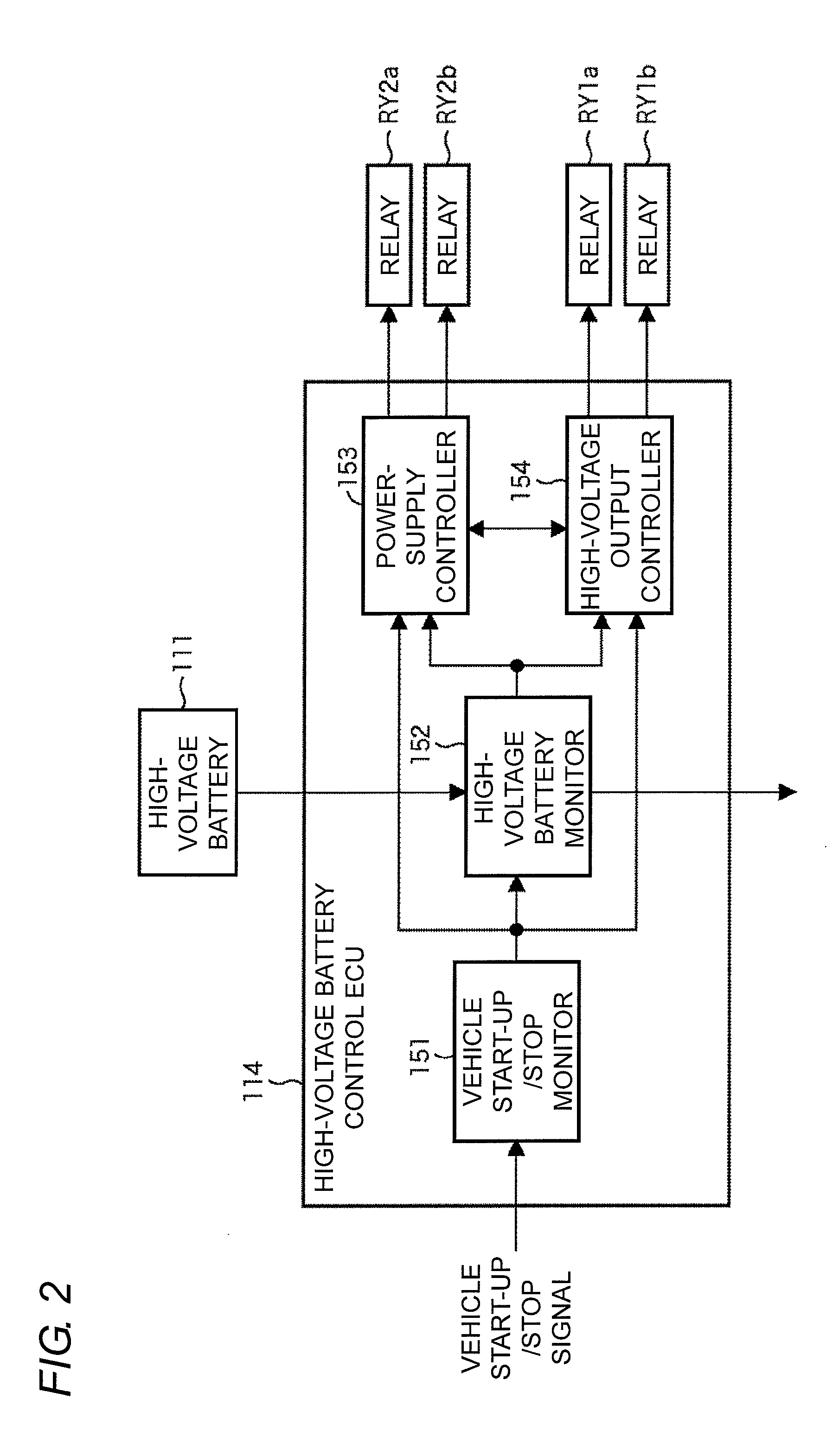
A power-supply control device for battery having a plurality of cells connected in series has a voltage conversion unit that steps down a voltage at the battery to supply the stepped-down voltage to a first load, a first opening and closing unit that opens and closes a supply path of first power from the battery to the voltage conversion unit and a second load, a battery control unit that detects abnormality of the battery, controls opening and closing of the first opening and closing unit, and is operated by second power supplied from the battery or third power supplied from the voltage conversion unit, the second power being lower than the first power, and a second opening and closing unit that opens and closes a supply path of the second power from the battery to the battery control unit.

Description

BACKGROUND OF THE INVENTION[0001]1. Technical Field[0002]The present invention relates to a power-supply control device, and particularly relates to a power-supply control device that is suitably used to control a power supply of an electric-powered vehicle.[0003]2. Related Art[0004]Two types of batteries, namely, a high-voltage battery and a low-voltage battery are usually provided in an electric-powered vehicle such as an EV (Electric Vehicle), an HEV (Hybrid Electric Vehicle), or a PHEV (Plug-in Hybrid Electric Vehicle).[0005]The high-voltage battery is mainly used as a power supply for a load of a high voltage (hereinafter, referred to as a high-voltage load) such as a main power motor for driving wheels of the electric-powered vehicle to travel and a compressor motor of an air conditioner.[0006]On the other hand, the low-voltage battery is mainly used as a power supply for a load of a low voltage (hereinafter, referred to as a low-voltage load) such as various ECUs (Electronic ...

Claims


Application Information

Patent Timeline
IPC IPC(8): H02J1/00
CPCB60L3/0046B60L3/04Y02T10/705Y02T10/7005B60L11/1851B60L58/10B60L58/12B60L58/18Y02T10/70
Inventor OMOTO, YASUMICHIIDO, YUSAKUHACHIYA, KOJI
Owner ORMON CORP
Learn More