
Method and apparatus for sequentially laminating optical film including polarizing film, to rectangular-shaped panel

a technology of optical film and polarizing film, applied in the direction of film/foil adhesive, instruments, other domestic objects, etc., can solve the problems of affecting the appearance of adjacent members

Inactive Publication Date: 2012-03-08
NITTO DENKO CORP
View PDF4 Cites 63 Cited by
  • Summary
  • Abstract
  • Description
  • Claims
  • Application Information

AI Technical Summary

Benefits of technology

[0055]As above, the present invention makes it possible to obtain optical film laminate sequential lamination method and apparatus capable of solving a problem in continuous lamination of an optical film laminate using a thin polarizing film having a thickness of 10 μm or less to have an overall thickness less than those of conventional optical film laminates.
[0056]As mentioned above, any case of using a thermoplastic resin substrate and subjecting a PVA type resin layer formed on the substrate to a uniaxial stretching to attain a stretching ratio of 5.0 or more cannot be found in prior art documents.
[0057]A representative example of a polarizing film production method and an example of a production method for a roll of an optical film laminate strip, for use in the present invention, will be specifically described below with reference to the following drawings.

Problems solved by technology

However, since the PVA type resins are hydrophilic and highly hygroscopic, a polarizing film produced using a PVA type resin is sensitive to changes in temperature and humidity, and more likely to expand and contract due to changes in surrounding environments, which is liable to cause the occurrence of crack.
Another problem when using a conventional polarizing film consisting of a PVA type resin layer is that expansion and contraction caused by environmental changes during use will produce stress in an adjacent member to which the polarizer film is joined, and thereby cause deformation, such as warp, in the adjacent member.
However, even in the optical film laminate where a triacetylcellulose (TAC) film serving as a protection film is laminated on each of opposite surfaces of a polarizing film, in cases where a single-layer polarizing film is used therein, there is a limit to thinning of the polarizing film.
Thus, expansion and contraction forces of the polarizing film become unignorable, and it is difficult to completely suppress the influence of expansion and contraction of the polarizing film, so that a certain level of expansion and contraction will inevitably occur in the optical film laminate including the polarizing film.
If expansion or contraction occurs in such an optical film laminate including a polarizing film, stress arising from the expansion or contraction will cause deformation, such as warp, in an adjacent member.
This deformation, even if it is small, leads to the occurrence of non-uniformity of display in a liquid-crystal display device.
Further, the contraction stress of the polarizing film will cause peeling or the like of the optical film laminate from a liquid-crustal panel.
However, the use of such a high-adhesion adhesive gives rise to a problem of difficulty in re-working which is an operation of, when the presence of an optical defect is found in a polarizing film of an optical film laminate laminated to a liquid-crystal display panel through a subsequent inspection, peeling the optical film laminate from the liquid-crystal display panel and laminating another optical film laminate to the liquid-crystal display panel.
This is one technical problem in a polarizing film to be obtained by the conventional method using a PVA type resin single-layer formed in a film shape.
The problem causes a growing demand for a new polarizing film production method, as an alternative to the conventional polarizing film production method using a PVA type resin single-layer, and being incapable of achieving a sufficient level of thinning of a polarizing film due to the above problem.
Specifically, it is virtually impossible to produce a polarizing film having a thickness of 10 μm or less by the conventional method using a PVA type resin single-layer formed in a film shape.
This is because, in producing a polarizing film using a film-shaped PVA type resin single-layer, if the thickness of the PVA type resin single-layer is excessively reduced, dissolution and / or breaking is likely to occur in a PVA type resin layer in a dyeing step and / or a stretching step, which makes it impossible to form a polarizing film having a uniform thickness.
As for the reason why the stretching ratio is restricted to 5.0 or less, the Patent Document 1 explains that a stretching at a high stretching ratio of greater than 5.0 makes it extremely difficult to maintain stable production.
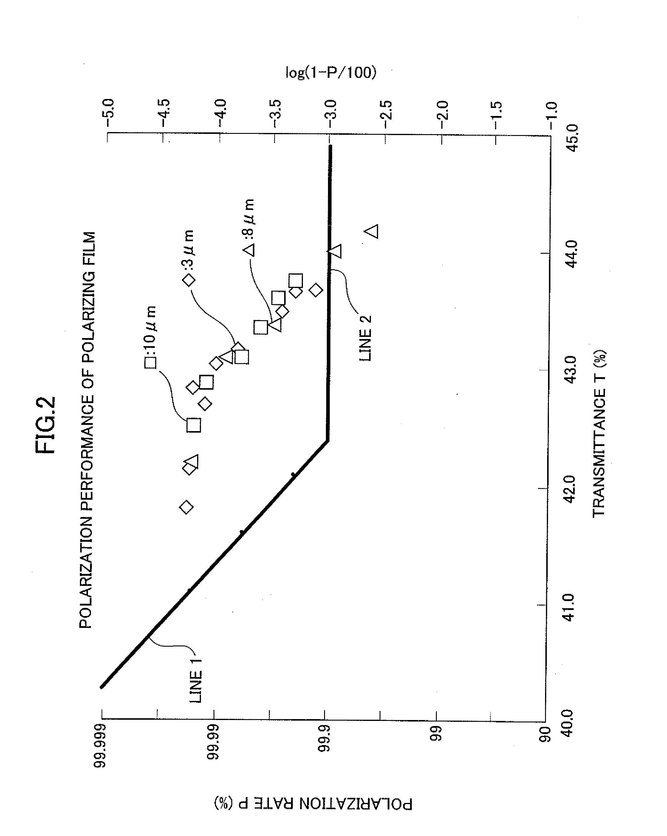
Thus, a polarizing film having an extremely small thickness of 2 to 4 μm, to be obtained by this method, is not enough to satisfy optical characteristics desired for a polarizing film to be used, for example, in an optical display device such as a liquid-crystal television, or an optical display device using an organic EL display element.

Method used


Image

  • Method and apparatus for sequentially laminating optical film including polarizing film, to rectangular-shaped panel
  • Method and apparatus for sequentially laminating optical film including polarizing film, to rectangular-shaped panel
  • Method and apparatus for sequentially laminating optical film including polarizing film, to rectangular-shaped panel

Examples


example 1

[0146]A continuous web of a substrate was prepared as a non-crystallizable ester type thermoplastic resin substrate comprising isophthalic acid-copolymerized polyethylene terephthalate copolymerized with 6 mol % of isophthalic acid (hereinafter referred to as “non-crystallizable PET”). The non-crystallizable PET has a glass transition temperature of 75° C. A laminate comprising the continuous web of non-crystallizable PET substrate and a polyvinyl alcohol (hereinafter referred to as “PVA”) layer was prepared in the following manner. By the way, PVA has a glass transition temperature of 80° C.

[0147]A non-crystallizable PET substrate having a thickness of 200 μm was prepared, and a PVA aqueous solution having a PVA concentration of 4 to 5 wt % was also prepared by dissolving a PVA powder having a polymerization degree of 1000 or more and a saponification degree of 99% or more in water. Then, the PVA aqueous solution was applied to the 200 μm-thick non-crystallizable PET substrate, and...

example 2

[0156]In the Example 2, as with the Example 1, a 7 μm-thick PVA layer was formed on a non-crystallizable PET substrate to form a laminate, and then the laminate including the 7 μm-thick PVA layer was subjected to a preliminary in-air stretching and stretched at a stretching ratio of 1.8 to form a stretched laminate, whereafter the stretched laminate was immersed in a dyeing solution containing iodine and potassium iodide and having a temperature of 30° C. to form a dyed laminate including an iodine-absorbed PVA layer. Differently from the Example 1, a process in the Example 2 additionally comprises a cross-linking step. The cross-linking step is designed to immerse the dyed laminate in a cross-linking boric acid aqueous solution at a temperature of 40° C., for 60 seconds, so as to allow PVA molecules of the iodine-absorbed PVA layer to be subjected to cross-linking. The cross-linking boric acid aqueous solution in this step was set to contain 3 weight parts of boric acid with respec...

example 3

[0160]In the Example 3, as with the Example 1, a 7 μm-thick PVA layer was formed on a non-crystallizable PET substrate to form a laminate, and then the laminate including the 7 μm-thick PVA layer was subjected to a preliminary in-air stretching and stretched at a stretching ratio of 1.8 to form a stretched laminate. Differently from the Example 1, a process in the Example 3 additionally comprises an insolubilization step. The insolubilization step is designed to immerse the stretched laminate in a boric acid insolubilizing aqueous solution at a solution temperature of 30° C., for 30 seconds, so as to insolubilize a PVA layer included in the stretched laminate and having oriented PVA molecules. The boric acid insolubilizing aqueous solution in this step was set to contain 3 weight parts of boric acid with respect to 100 weight parts of water. A technical effect expected of the insolubilization step in the Example 3 is to prevent the PVA layer included in the stretched laminate from b...


PUM

PropertyMeasurementUnit
thicknessaaaaaaaaaa
thicknessaaaaaaaaaa
thicknessaaaaaaaaaa

Abstract

A method of sequentially laminating a carrier film-attached optical film laminate to a rectangular-shaped panel having a long side and a short side, is provided. The optical film laminate includes an optical film including a thin polarizing film, and a carrier film attached to the optical film through an adhesive layer. The method includes the steps: forming a plurality of slits in the carrier film-attached optical film laminate in a width direction thereof at lengthwise given intervals to extend from a surface of the optical film on a side opposite to the carrier film to a depth reaching a surface of the carrier film adjacent to the optical film to thereby form an optical film sheet supported by the carrier film, between lengthwisely adjacent two of the slits; and laminating each of the optical film sheets to a respective one of the panels through the adhesive layer.

Description

TECHNICAL FIELD[0001]The present invention relates to a method and an apparatus for sequentially laminating an optical film including a polarizing film, to a rectangular-shaped panel. In particular, the present invention relates to a method of sequentially laminating an optical film including an extremely thin polarizing film having a thickness of 10 μm or less, to a panel.BACKGROUND ART[0002]There is a widely known method in which a single layer made of a polyvinyl alcohol type resin (hereinafter referred to as “PVA type resin”) formed in a film shape is subjected to dyeing and stretching to produce a polarizing film comprising a PVA type resin layer, wherein molecules of the PVA type resin are oriented in the direction of the stretching, and a dichroic material is absorbed (impregnated) in the PVA type resin in a molecularly oriented state. The thickness of a polarizing film to be obtained by the above conventional method using a PVA type resin single-layer film is in the range of...

Claims


Application Information

Patent Timeline
Patent Type & Authority Applications(United States)
IPC IPC(8): B32B37/14B32B38/18B32B38/04B32B38/10B32B37/02B32B37/12
CPCB32B37/203B32B38/04B32B38/1808B32B38/1858B32B2037/1223B32B2037/268Y10T156/1304B32B2038/047B32B2309/105B32B2457/202B32B2457/206G02B5/3033B32B2038/0028C09J5/00C09J7/22C09J7/29C09J7/38C09J2203/318C09J2301/302C09J2301/40G02B5/3025G02B5/305B29L2011/0016C08J5/18G02B5/1852G02B5/3041
Inventor KITAGAWA, TAKEHARUNAKAZONO, TAKUYAGOTO, SHUSAKUMIYATAKE, MINORUMORI, TOMOHIROKAMIJO, TAKASHI
Owner NITTO DENKO CORP
Learn More