
Foam laminate product and process for production thereof

a technology of foam laminate and foam, which is applied in the field of foam laminate products, can solve the problems of relatively poor sound absorption, poor sound absorption properties, etc., and achieve the effects of reducing air flow resistance, avoiding scrim, and improving acoustic properties

Inactive Publication Date: 2012-03-01
PROPRIETECT LP
View PDF7 Cites 4 Cited by
  • Summary
  • Abstract
  • Description
  • Claims
  • Application Information

AI Technical Summary

Benefits of technology

The present invention provides a laminate product with improved acoustical properties and a relatively low air flow resistance. The laminate product comprises a foam core with a cover layer, where the cover layer comprises a fibrous reinforcement layer that is substantially encapsulated by a polymer. The laminate product has a porous structure that results in relatively low air flow resistance and improved sound absorption properties. The invention also allows for the replacement of conventional polyethylene film with a more cost-effective and readily available fibrous polymer layer, which can be made available in different weights, colors, and textures. The laminate product can be used in various applications such as vehicular headliners, floorboards, and cargo vehicle mats.

Problems solved by technology

This results in products that have relatively poor sound absorption properties.
The poor sound absorption properties are related to the air flow resistance properties of the product.
A product with high air flow resistance (i.e., relatively impermeable to the passage of air) tends to have relatively poor sound absorption properties whereas a product with low air flow resistance (i.e., relatively permeable to air) tends to have relatively good sound absorption properties.

Method used


Image

  • Foam laminate product and process for production thereof
  • Foam laminate product and process for production thereof
  • Foam laminate product and process for production thereof

Examples


examples 1-3

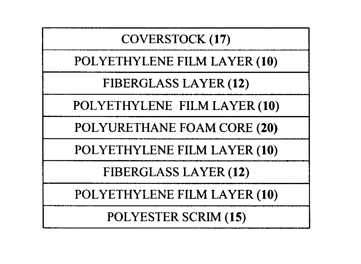
[0106]Example 1 was produced using a blank having the following lay-up:

PEFRLPEFCPEFRLPESCM

example 1

is provided for comparative purposes only and is outside the scope of the present invention.

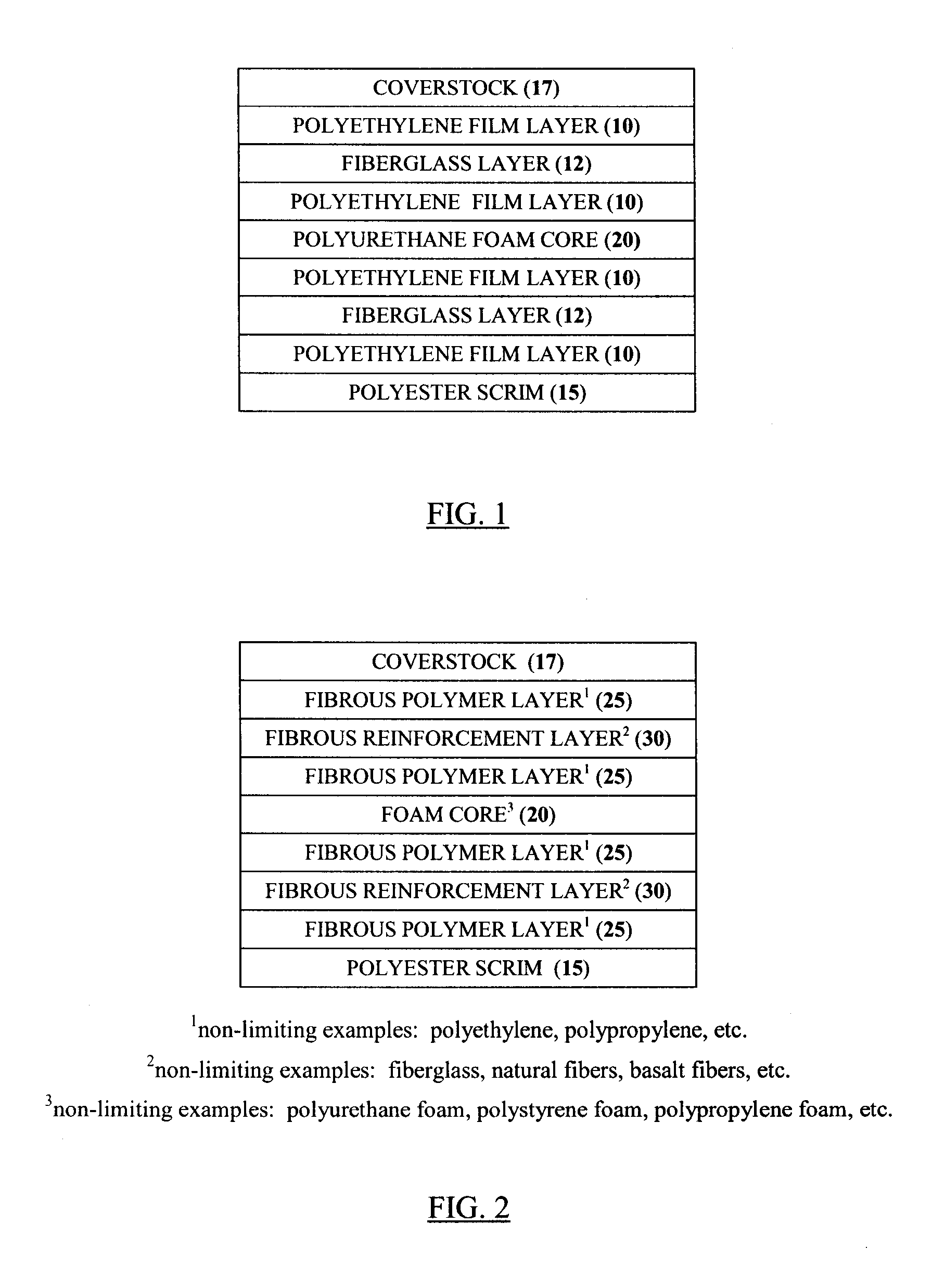
[0107]Examples 2 and 3 were produced using blanks having the following lay-ups:

FPL#1FRLFPL#1FCFPL#1FRLFPL#1SCM

FPL#2FRLFPL#2FCFPL#2FRLFPL#2SCM

[0108]Each blank or stack was manually passed through a flat bed laminator, consisting of an adjacent heating zone and cooling zone. The process parameters for lamination were as follows:[0109]line speed: 9 m / min-12 m / min;[0110]hot Platens temp.: 175° C.-240° C.;[0111]pressure roller offset: 1.8 mm;[0112]plate height 5.2 mm; and[0113]cold platens temperature: 20° C.-45° C.

The resulting samples were conditioned for 24 hours.

[0114]Thereafter the samples were heated and shaped in a laminator such as the one described in U.S. Pat. No. 5,928,597 [Van Ert], U.S. Pat. No. 6,146,578 [Van Ert el al.] and U.S. Pat. No. 6,338,618 [Van Ert et al.] to produce the final form of the samples. The process conditions for this part of the process were as follows:[0115]inf...

examples 4-5

[0125]Typically, the foamed isocyanate-based polymer is produced from a reaction mixture which comprises an isocyanate and an active hydrogen-containing compound.

[0126]Examples 4 and 5 were produced using the methodology used in Examples 1-3 and blanks having the following lay-ups:

PEFRLPEPEFRLPEFCPEFRLPESCM

FPL#1FRLFPL#1FPL#1FRLFPL#1FCFPL#1FRLFPL#2SCM

[0127]Example 4 is provided for comparative purposes only and is outside the scope of the present invention.

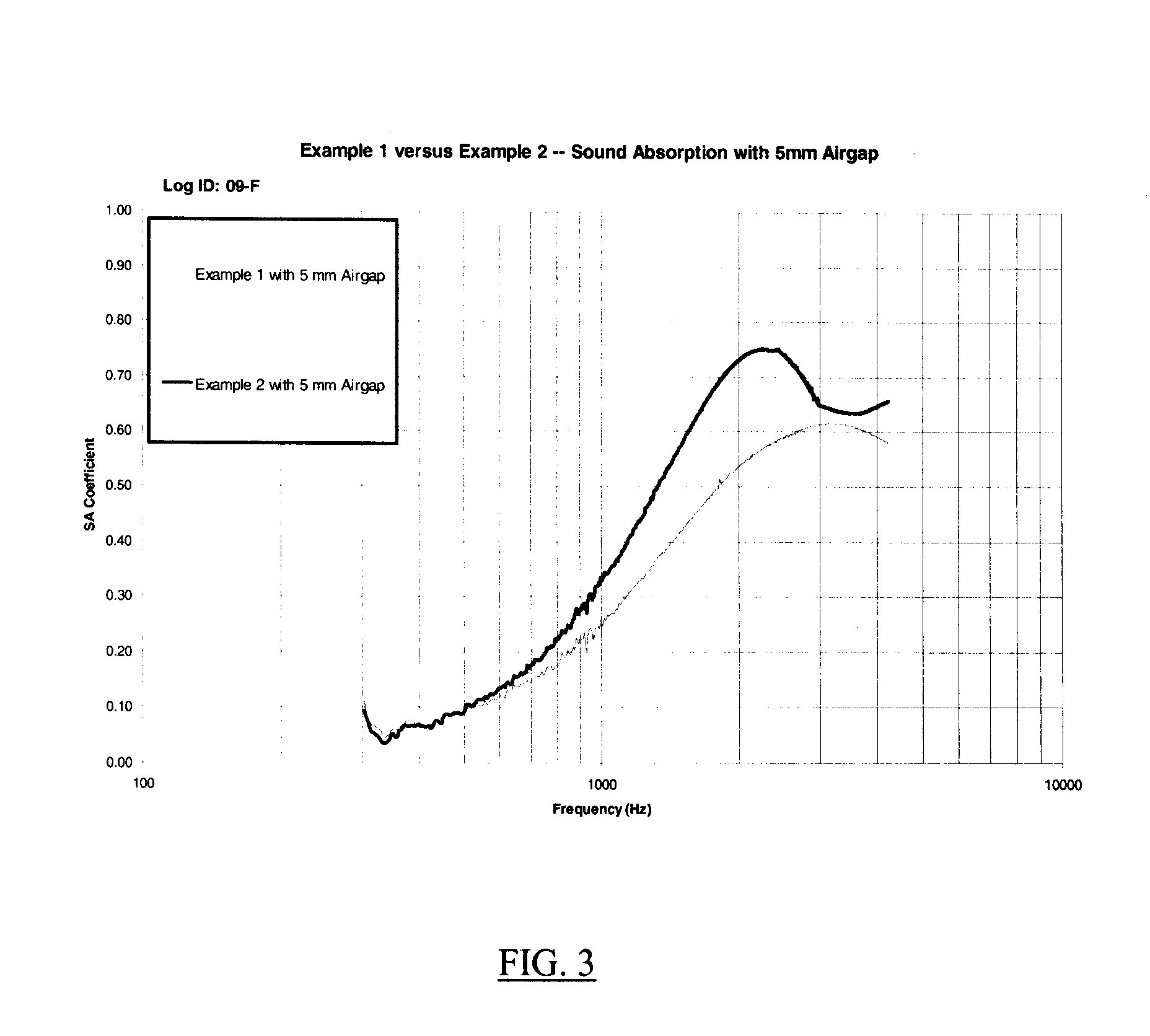
[0128]The result samples were subjected to the same physical testing reporting in connection with Examples 1-3 and the results are reported in Table 2 (weight, maximum load, strength and air flow resistance) and FIG. 4 (sound absorption). The same trends reported in connected with the results for Examples 1-3 are seen in the results for Examples 4-5.


PUM

PropertyMeasurementUnit
thicknessaaaaaaaaaa
thicknessaaaaaaaaaa
thicknessaaaaaaaaaa

Abstract

A laminate product comprising a foam core having a pair of opposed major surfaces and a cover layer secured with respect to each major surface is described. The cover layer contains a fibrous reinforcement layer that is substantially encapsulated by a polymer. It has been found that the use of a fibrous polymer layer (e.g., in place of conventional polyethylene film) results in a laminate product having significantly lower resistance to air flow resistance and significantly improved sound absorption properties.

Description

CROSS-REFERENCE TO RELATED APPLICATION[0001]The present application claims the benefit under 35 U.S.C. §119(e) of provisional patent application S. N. 61 / 202,249, filed Feb. 10, 2010, the contents of which are hereby incorporated by reference.BACKGROUND OF THE INVENTION[0002]1. Field of the Invention[0003]In one of aspects the present invention relates to a foam laminate product, more particularly such a product adapted for use in the interior of a vehicle. In another of its aspects, the present invention relates to process for the production of a foam laminate product. In a highly preferred embodiment, the present invention relates to a headliner, more particularly a vehicular headliner. In this preferred embodiment, an aspect of present invention relates to process for the production of a headliner.[0004]2. Description of the Prior Art[0005]Energy absorbing devices (also known as energy management devices) and structural devices are known. Such devices can take one of a variety of...

Claims


Application Information

Patent Timeline
Patent Type & Authority Applications(United States)
IPC IPC(8): B32B3/26B32B7/12B32B27/08B32B27/12
CPCB29C44/5681B29K2075/00B29K2105/128B29L2031/3023B32B5/18B60R13/0212B32B37/04B32B2305/022B32B2305/20B32B2307/102B32B2605/003B32B5/28Y10T428/249982Y10T428/249953B32B5/245B32B2266/0278B29C66/73182B29C43/003
Inventor GEHANI, NEIL P.
Owner PROPRIETECT LP
Learn More