
Method and apparatus for control of fault-induced delayed voltage recovery (FIDVR) with photovoltaic and other inverter-based devices

a technology of photovoltaic and inverter, which is applied in the direction of emergency power supply arrangements, magnets, magnetic bodies, etc., can solve the problems of significant load loss, significant voltage loss, and significant voltage loss of a region of the t&d system for several seconds after the faul

Active Publication Date: 2012-03-01
GENERAL ELECTRIC CO
View PDF1 Cites 22 Cited by
  • Summary
  • Abstract
  • Description
  • Claims
  • Application Information

AI Technical Summary

Benefits of technology

"The patent text describes a system for correcting motor stalls and supporting the electric power grid. The system includes an inverter-based electric power generation device and an electric power inverter assembly, which are coupled together. A controller is also included, which is programmed to modulate the real current and reactive current as a function of the electric power grid frequency and voltage. The system can inject real current and reactive current into the grid to support it during periods of low voltage conditions caused by a fault-induced delayed voltage recovery (FIDVR). The technical effect of this system is to provide a reliable and flexible solution for supporting the electric power grid and preventing motor stalls."

Problems solved by technology

Such electrical faults typically automatically initiate fault-clearing features of the T&D system that quickly isolate the fault within approximately three cycles, however, the voltage of a region of the T&D system may remain at a significantly reduced level for several seconds after the fault has been cleared.
The extended period of voltage depression is typically caused by high concentrations of induction motor loads with constant torque and low inertia that begin to slow down and have flux collapse substantially simultaneously with the voltage reduction and may slow down sufficiently to stall under their associated loading.
However, the increased current at low voltage conditions may not unstall the motor, that is, the rotor will not be released from the locked-rotor condition.
The heavy locked-rotor current demands on the T&D system result in T&D system voltage remaining significantly depressed for a period of time, typically a few seconds, after the fault is cleared, thereby leading to a first cascading effect, i.e., a cascading voltage collapse through adjacent portions of the interconnected T&D system that may extend further through the utility power grid.
The combined effect of larger induction motors and smaller induction motors tripping over such a short period of time may result in significant load loss, as can the loss of generation described above, with a potential effect of a voltage recovery overshoot inducing a high-voltage condition.
At least some known T&D systems may be configured to receive retrofit protection systems that facilitate clearing faults more quickly, however, FIDVR events that are initiated within as little as 3 cycles will not be prevented.
However, these two potential solutions require extended time periods to design, construct, and install and in general, may not be sufficient to mitigate FIDVR events.
They also require large physical footprints, significant capital investment, and long-term operational and maintenance costs.
Moreover, at least some known T&D systems may be configured to receive retrofit UV load shedding schemes to trip stall-prone loads as soon as possible once the fault condition is detected, however, such load shedding schemes typically require at least partial power outages to some portions of the T&D system.
This solution may take decades to implement and may encounter significant public reluctance to pay more for residential A / C units, thereby extending the time horizon for substantial implementation.

Method used


Image

  • Method and apparatus for control of fault-induced delayed voltage recovery (FIDVR) with photovoltaic and other inverter-based devices
  • Method and apparatus for control of fault-induced delayed voltage recovery (FIDVR) with photovoltaic and other inverter-based devices
  • Method and apparatus for control of fault-induced delayed voltage recovery (FIDVR) with photovoltaic and other inverter-based devices

Examples


Embodiment Construction

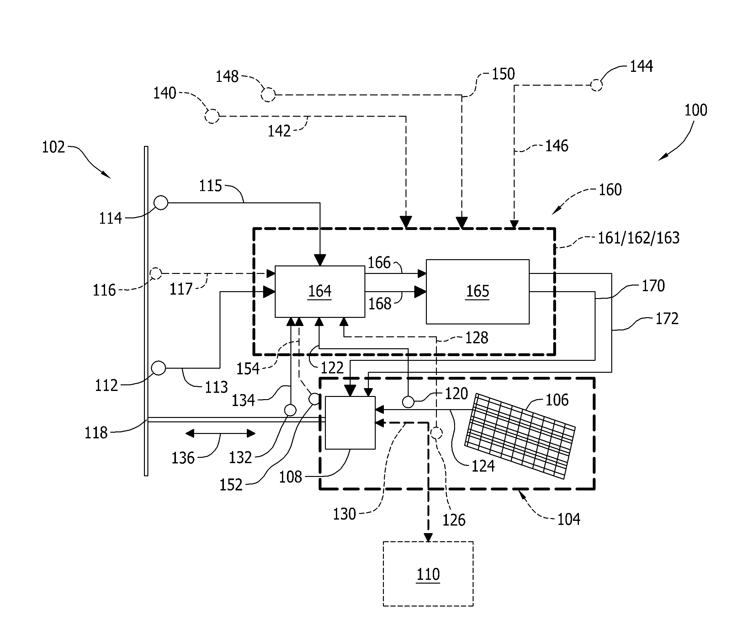
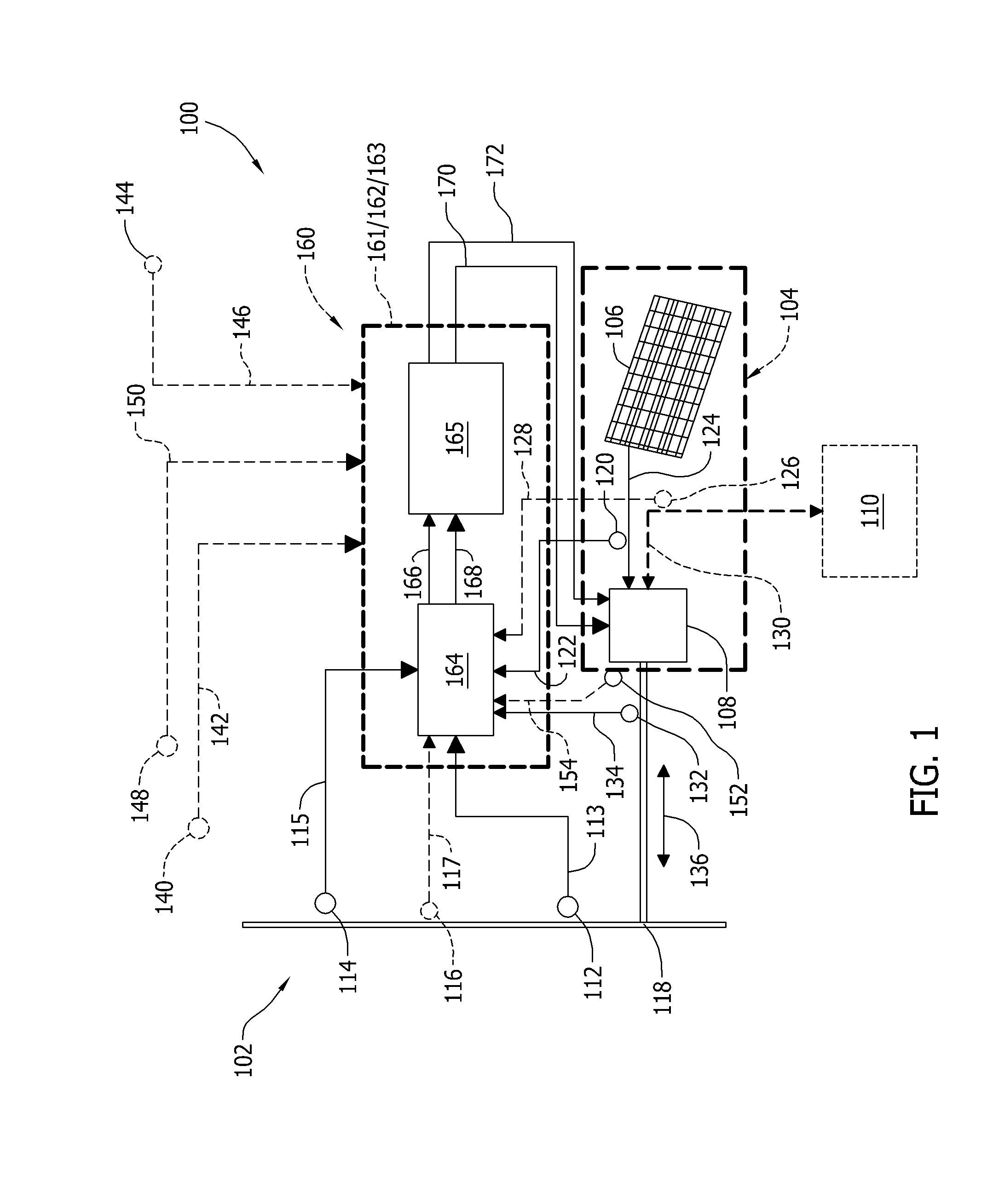
[0015]The embodiments described herein provide an electric power grid support system. An inverter-based fault-induced delayed voltage recovery (FIDVR) system is implemented in the hardware and software of the electric power grid support system to reduce an extent and duration of voltage dips on the electric power grid to facilitate early avoidance of, and recovery from, FIDVR events. The embodiments described herein use a photovoltaic (PV) device, such as a roof-top residential solar panel, physically located in close vicinity to air-conditioning (A / C) compressor-drive induction motors. In one embodiment, the grid support system uses inputs that include grid frequency and grid voltage to determine an optimum amount of real current and reactive current to inject into the grid to provide sufficient torque on stalled induction rotors to facilitate release from a locked-rotor, or stalled condition, including induction motors approaching stall conditions. In another embodiment, the grid ...


PUM

PropertyMeasurementUnit
frequenciesaaaaaaaaaa
frequencyaaaaaaaaaa

Abstract

A method of assembling a motor stall correction system includes coupling an inverter-based electric power generation device to an electric power inverter assembly. The method also includes coupling the electric power inverter assembly to at least one induction motor. The method further includes operatively coupling at least one controller to the electric power inverter assembly. The controller is programmed to transmit electric current from the inverter-based electric power generation device to the electric power inverter assembly. The controller is also programmed to transmit real current and reactive current from the electric power inverter assembly to the induction motor. The controller is further programmed to modulate the real current and the reactive current as a function of at least one of an electric power grid frequency and an electric power grid voltage.

Description

BACKGROUND OF THE INVENTION[0001]The subject matter described herein relates generally to utility grid support and, more particularly, to methods and apparatus for facilitating control of a fault-induced delayed voltage recovery (FIDVR) on a utility grid using photovoltaic devices.[0002]Many known electric utility grids include a plurality of interconnected known transmission and distribution (T&D) systems. Many of these known T&D systems include a plurality of interconnected regions that are geographically defined by T&D system features, for example, substation locations. In at least some known T&D regions, a significant concentration of known induction motors are present. Many of these known induction motors have constant-torque features and low-inertia characteristics. Examples of such constant-torque, low-inertia induction motors include residential and commercial air-conditioner (A / C) compressor motors. Moreover, many of these known residential A / C compressor motors are commerc...

Claims


Application Information

Patent Timeline
Patent Type & Authority Applications(United States)
IPC IPC(8): H02J9/00H05K13/00
CPCH02J3/383Y02E10/563Y10T29/4902Y02B10/12Y02B10/14H02J3/1821Y02E40/30H02J2300/24H02J3/381Y02B10/10Y02E10/56H02J3/12H02J3/16
Inventor MILLER, NICHOLAS W.DELMERICO, ROBERT WILLIAMWALLING, REIGH ALLENLARSEN, EINAR VAUGHN
Owner GENERAL ELECTRIC CO
Learn More