
Vehicle partition side member structure

a technology of side member and vehicle body, which is applied in the direction of vehicle arrangement, transportation and packaging, transportation items, etc., can solve the problems that the rigidity of the closed cross section of the trunk hinge bracket cannot be improved, and the rigidity of the closed cross section of the trunk hinge bracket cannot be achieved. , to achieve the effect of avoiding excessive weight increase, improving rigidity around the closed cross section, and increasing flexibility

Inactive Publication Date: 2012-03-01
SUZUKI MOTOR CORP
View PDF5 Cites 4 Cited by
  • Summary
  • Abstract
  • Description
  • Claims
  • Application Information

AI Technical Summary

Benefits of technology

[0013]The present invention has been made in view of the foregoing circumstances. An object of the present invention is to provide a structure of a partition side member having the following advantages over a conventional structure. Specifically, the structure of the present invention is capable of: providing increased flexibility of a hinge layout while securing joint rigidity of a partition reinforcement, by allowing a flat portion of a partition panel to be provided closer to a front side of a vehicle than before; having improved rigidity around a closed cross section while avoiding an excessive weight increase; and providing improved rigidity of a vehicle body as a whole in such a way that a vehicle front side of a partition side panel having a large plate thickness is joined to a quarter panel to thereby firmly join a member extending in a vehicle width direction to vehicle body side members.

Problems solved by technology

However, the conventional vehicle body structures as described above cannot achieve improvement in the rigidity of the closed cross section unless the panels that form the closed cross section are firmly joined together.
However, if these positions are not appropriate, the rotation trajectory of the trunk door has a problem, and therefore a complicated link mechanism needs to be employed as a countermeasure.
Therefore, the trunk hinge brackets may not achieve sufficient attachment rigidity.

Method used


Image

  • Vehicle partition side member structure
  • Vehicle partition side member structure
  • Vehicle partition side member structure

Examples


Embodiment Construction

[0032]The present invention will be described below in detail based on an illustrated embodiment.

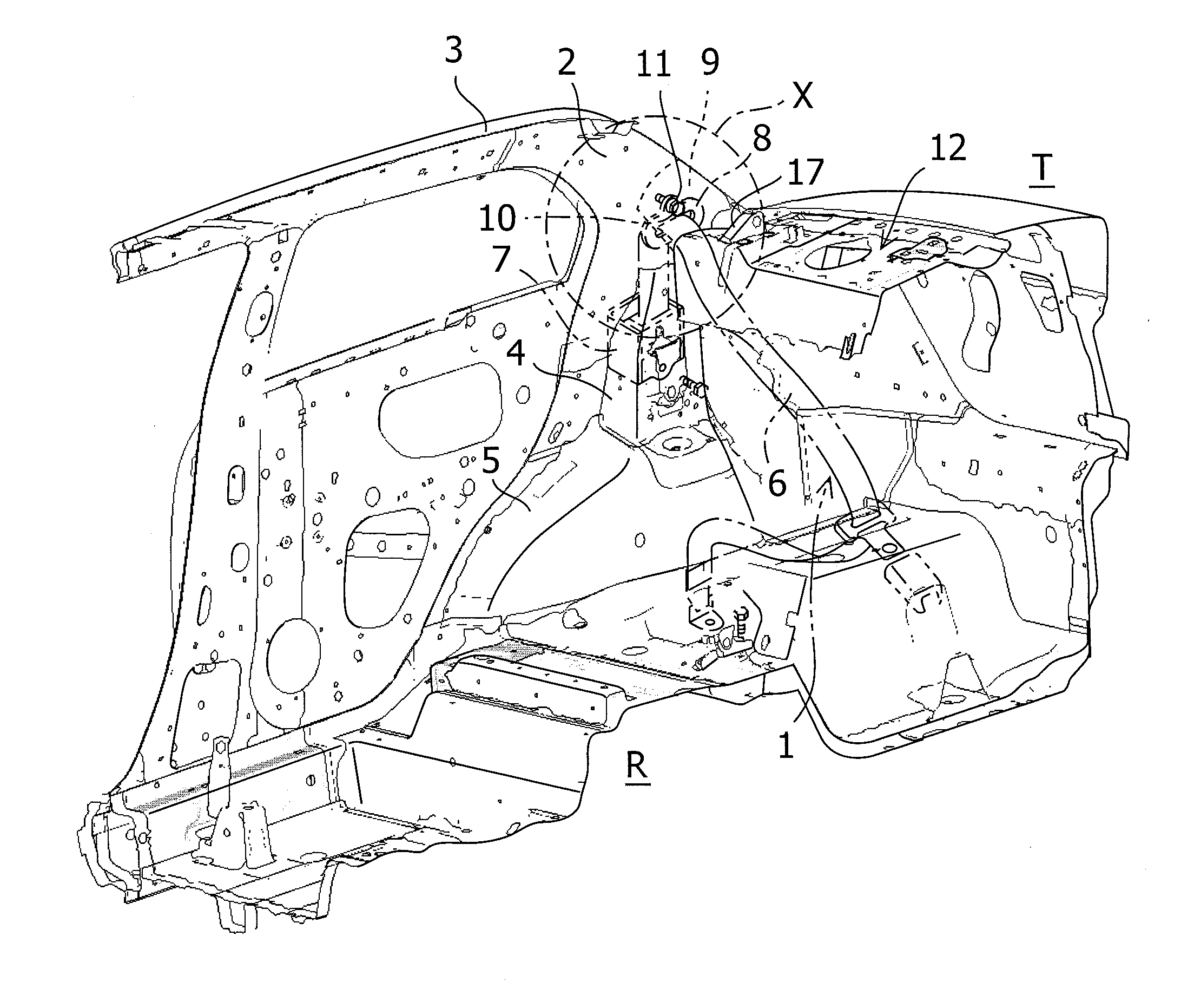
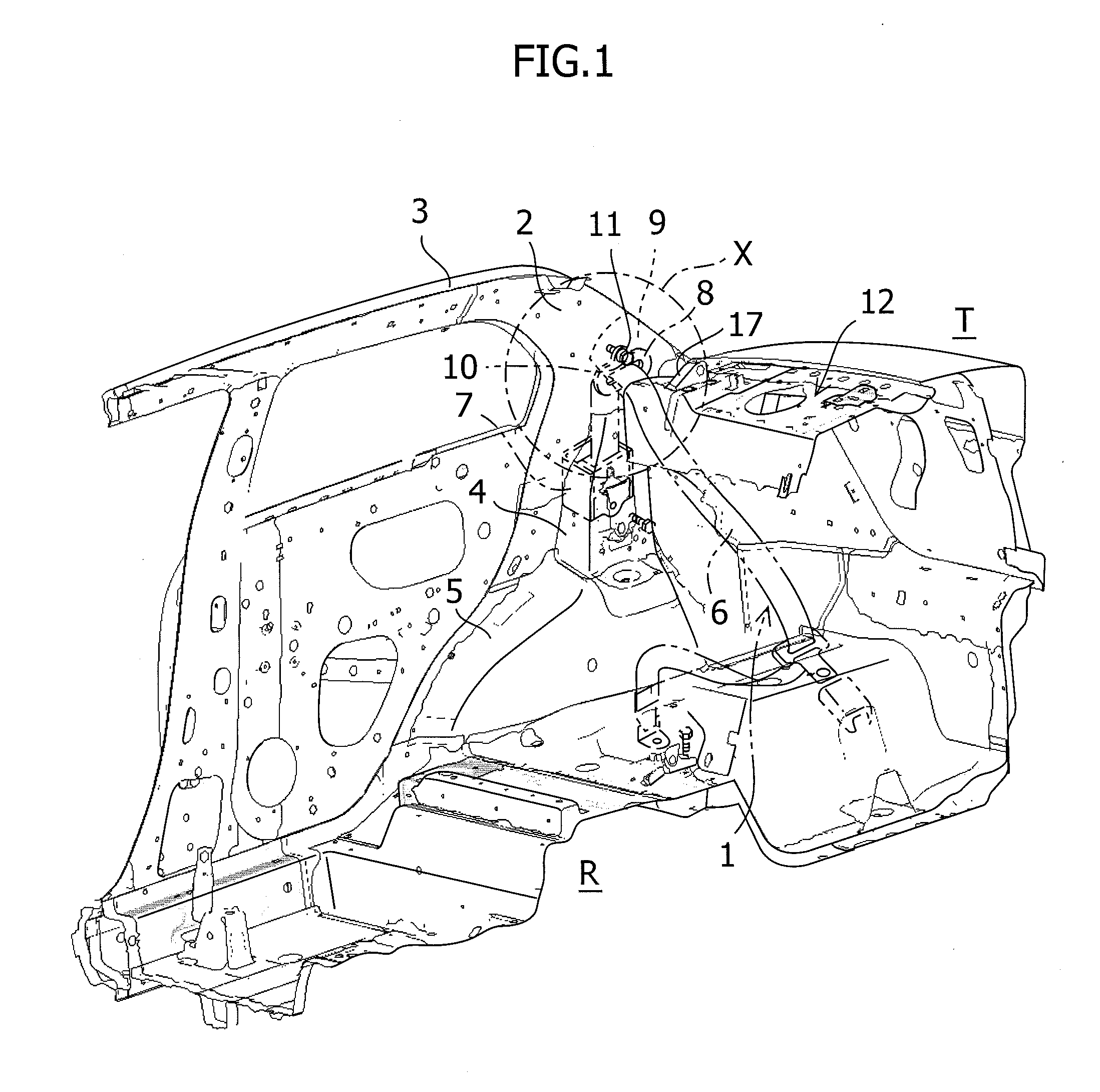
[0033]FIG. 1 to FIG. 6 show a structure of a partition side member according to an embodiment of the present invention.

[0034]As shown in FIG. 1 to FIG. 6, a vehicle according to the embodiment of the present invention is an automobile of a four-door sedan type equipped with a seat belt apparatus 1 configured to hold a passenger on a backseat. A side vehicle body structure of the vehicle of this type includes a quarter inner panel 2, a quarter outer panel 3, a rear pillar panel 4, and a wheel house inner panel 5, which form a side vehicle body of the vehicle by extending in a vehicle front-rear direction and a vehicle vertical direction.

[0035]The seat belt apparatus 1 includes a retractor 7 configured to rewind a rear seat belt 6, and a seat belt guide 8 configured to guide and support an intermediate position of the rear seat belt 6 to be unwound upward from the retractor 7. The retracto...


PUM


Abstract

A partition side member structure includes a partition panel, partition side panels joined to both right and left sides of the partition panel, and a partition reinforcement joined to backsides of the partition panel and the partition side panels. The partition side panels are divided in a vehicle front-rear direction into two partition side panels, which are front and rear partition side panels, by a dividing line extending in a vehicle width direction on a substantially horizontal plane formed of joining portions of the front and rear partition side panels. An upper part of the partition reinforcement is joined to a front portion of the rear partition side panel bent downward and a lower part of the partition reinforcement is joined to a lower portion of the front partition side panel bent downward.

Description

CROSS-REFERENCE TO RELATED APPLICATIONS[0001]The present application claims the benefit of Japanese Patent Application No. 2010-192007, filed Aug. 30, 2010, the disclosure of which is incorporated by reference herein.BACKGROUND OF THE INVENTION[0002]1. Field of the Invention[0003]The present invention particularly relates to a structure of a partition side member of a notchback type vehicle.[0004]2. Description of Related Art[0005]In a vehicle, a partition panel is provided at a rear part of a vehicle body in order to partition the vehicle body into a vehicle interior and a luggage compartment (a luggage space or a trunk space). This partition panel is located at a vertically middle position in the rear part of the vehicle body and has a function of a component that contributes to the vehicle body rigidity, that is, torsional rigidity, in particular, of the rear part. In other words, an improvement in rigidity of the partition panel enables improvement in driving stability of the ve...

Claims


Application Information

Patent Timeline
Patent Type & Authority Applications(United States)
IPC IPC(8): B62D25/02
CPCB62D25/087B62D25/02
Inventor SAKAI, NAOKI
Owner SUZUKI MOTOR CORP
Learn More