Keycap, keyboard with the same, jig for painting the same

a keycap and key plate technology, applied in the field of keys, can solve the problems of easy disengagement of painted keycaps from keyboard plates, inability to install painted keycaps stably, etc., and achieve the effect of reducing the probability of disengagemen

Inactive Publication Date: 2012-03-01
CHICONY ELECTRONICS
View PDF9 Cites 4 Cited by
  • Summary
  • Abstract
  • Description
  • Claims
  • Application Information

AI Technical Summary

Benefits of technology

[0015]In the embodiment of the invention, the keycap further comprises a jig connection structure. When the keycap is in painting process, the keycap is mounted on the jig by the jig connection structure. Therefore, in the painting process, the plate connection structure which is set for connecting with the plate is not connected to the jig directly. Hence, the shape / size of plate connection structure is not changed after the painting process. When the painting process is finished, the keycap is installed on the plate by the plate connection structure. It can reduce the disengaging probability between the keycap and the plate.

Problems solved by technology

Hence, the painted keycap could not be installed on the keyboard plate stably.
Furthermore, the painted keycap may disengage from the keyboard plate easily.

Method used


Image

  • Keycap, keyboard with the same, jig for painting the same
  • Keycap, keyboard with the same, jig for painting the same
  • Keycap, keyboard with the same, jig for painting the same

Examples


Embodiment Construction

[0023]Reference will now be made in detail to the present embodiments of the invention, examples of which are illustrated in the accompanying drawings. Wherever possible, the same reference numbers are used in the drawings and the description to refer to the same or like parts.

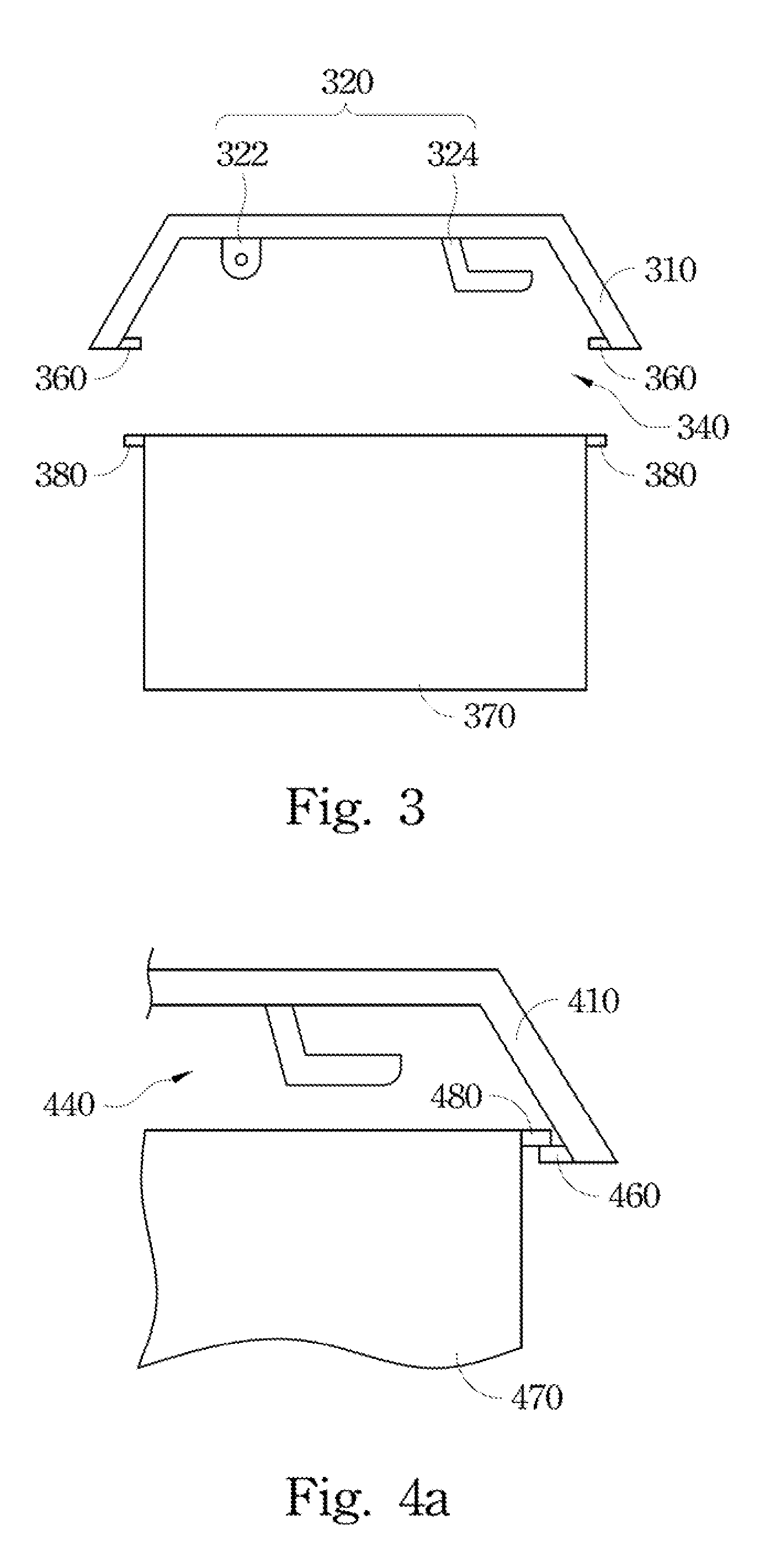
[0024]All embodiments of the invention include an additional connection structure for connecting with the jig, and the connection structure for connecting with the plate is not connected to the jig directly. Therefore, the shape / size of the connection structure for connecting with the plate is not changed in the painting process.

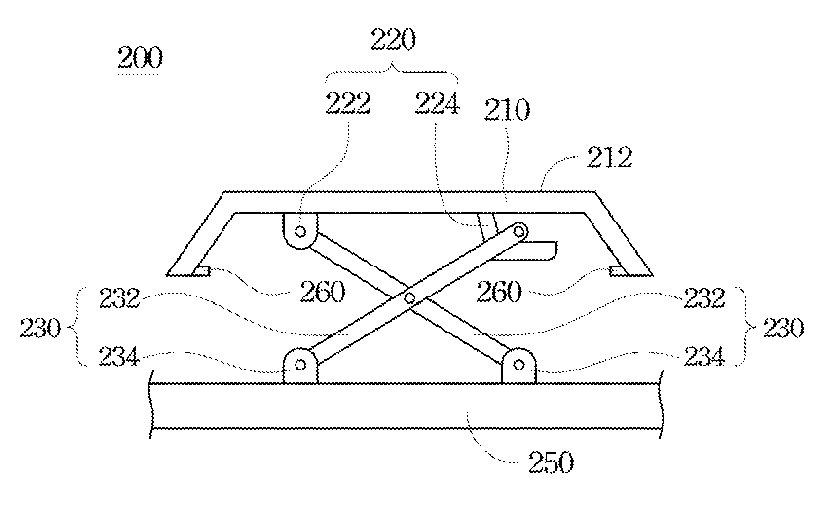
[0025]Please refer to FIG. 1. FIG. 1 illustrates a cross-section view of one keycap assembly. Keyboard 100 has a plate 150 and a keycap 110. The plate 150 includes a keycap connection structure 130. The keycap 110 is set on the plate 150. The keycap 110 could movie vertically relative to the plate 150 to form a moving path. The keycap 110 includes a press surface 112, hollow zone 140, ...


PUM


Abstract

A keycap is disposed on the plate of a keyboard. The keycap comprises a press surface, a hollow zone, a plate connection structure, a jig connection structure. The hollow zone is set on a side of the keycap opposite to the press surface. The plate connection structure is set in the hollow zone and used for connecting to the plate. The jig connection structure is connected to the jig when the keycap in a painting processing. Moreover, a keyboard and a jig for the keycap are also provided herein.

Description

RELATED APPLICATIONS[0001]This application claims priority to Taiwan Application Serial Number 99216499, filed Aug. 26, 2010, which is herein incorporated by reference.BACKGROUND[0002]1. Field of Invention[0003]The present invention relates to a keycap. More particularly, the present invention relates to a keyboard with a keycap and a jig for painting the keycap.[0004]2. Description of Related Art[0005]The keycap of the keyboard could be moved vertically relative to the keyboard plate by the cooperation of the connected structures set on the keycap and set on the keyboard plate.[0006]In some situation, the keycap is painted to provide a variety of looks. The keycap is mounted on the jig first, and then after the painting, baking, and printing process, the keycap is taken out from the jig and installed on the keyboard plate.[0007]A conventional jig has a connected structure similar to the connected structure of the keyboard plate. Hence, the connected structure of the keycap can be c...

Claims


Application Information

Patent Timeline
Patent Type & Authority Applications(United States)
IPC IPC(8): H01H13/76B23Q3/00H01H13/14
CPCH01H3/125H01H11/00H01H13/14H01H2229/00H01H2219/028H01H2221/00H01H13/88
Inventor TSAI, CHING-CHENG
Owner CHICONY ELECTRONICS
Why Eureka
Try Eureka