
System and method for multiphase pump lubrication

a multi-phase screw pump and lubrication technology, applied in the direction of liquid degasification, separation processes, borehole/well accessories, etc., can solve the problem of adding costs and maintenance to the screw pump system

Active Publication Date: 2012-03-01
VETCO GRAY SCANDINAVIA
View PDF2 Cites 33 Cited by
  • Summary
  • Abstract
  • Description
  • Claims
  • Application Information

AI Technical Summary

Benefits of technology

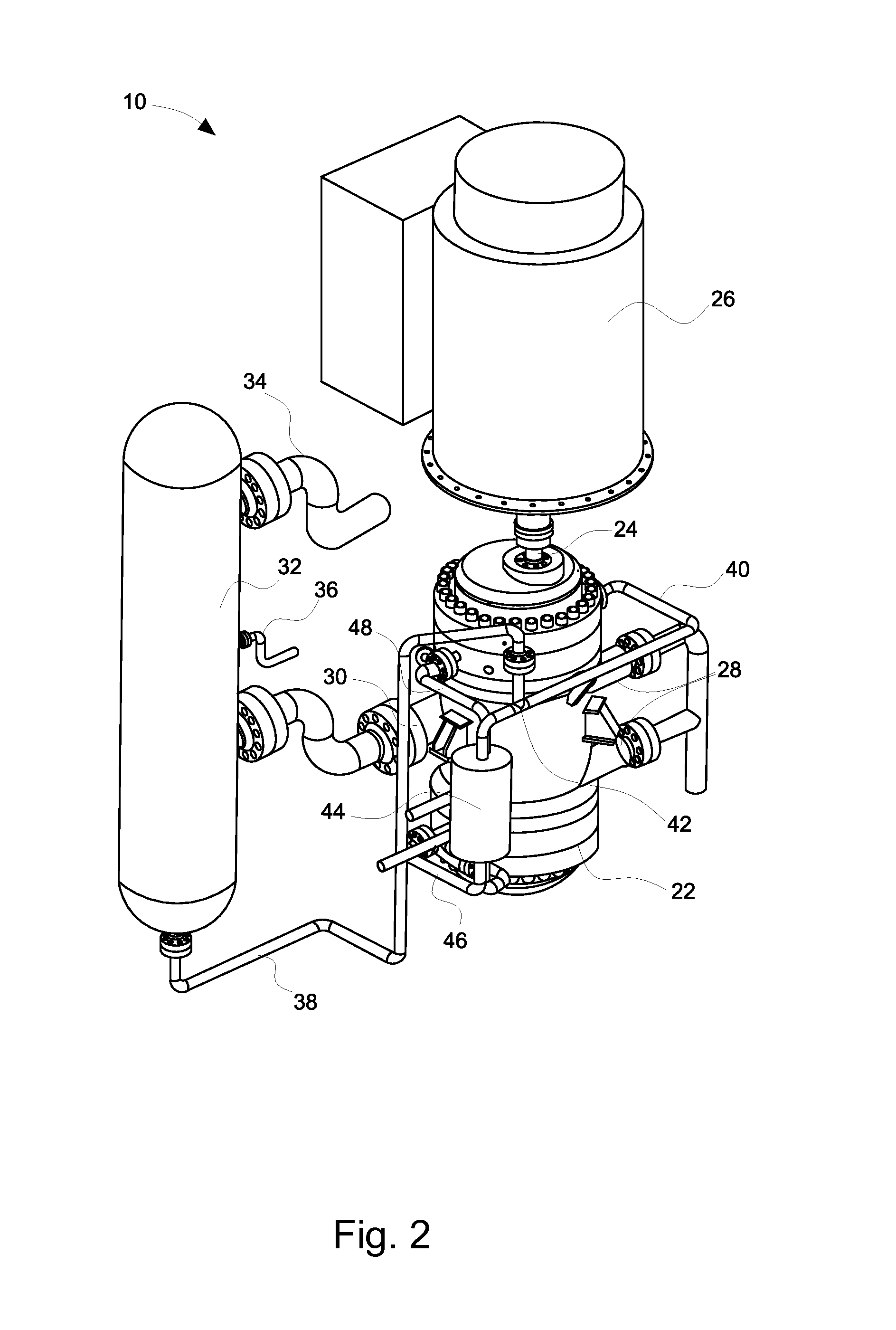
[0007]In a third embodiment, a method of operating a subsea system includes transferring a multiphase fluid from an outlet of a multiphase pump to an inlet of a multiphase separator, facilitating separation of a solid phase and a liquid phase from the multiphase fluid using a solid-liquid separation device disposed in a shell of the multiphase separator, facilitating separation of a gas phase and the liquid phase from the multiphase fluid using a gas-liquid separation device disposed in the shell of the multiphase separator, maintaining a volume of the liquid phase in a liquid reservoir disposed in the shell of the multiphase separator, transferring the liquid phase from the liquid reservoir to lubricated components of the multiphase pump, and lubricating the lubricated components of the multiphase pump with the liquid phase.

Problems solved by technology

Such a lubricant flush system may require additional components and maintenance, which adds costs and maintenance to the screw pump system.

Method used


Image

  • System and method for multiphase pump lubrication
  • System and method for multiphase pump lubrication
  • System and method for multiphase pump lubrication

Examples


Embodiment Construction

[0019]While the present disclosure may be susceptible to various modifications and alternative forms, specific embodiments have been shown by way of example in the drawings and tables and have been described in detail herein. However, it should be understood that the embodiments are not intended to be limited to the particular forms disclosed. Rather, the disclosure is to cover all modifications, equivalents, and alternatives falling within the spirit and scope of the disclosure as defined by the following appended claims. Further, although individual embodiments are discussed herein, the disclosure is intended to cover all combinations of these embodiments.

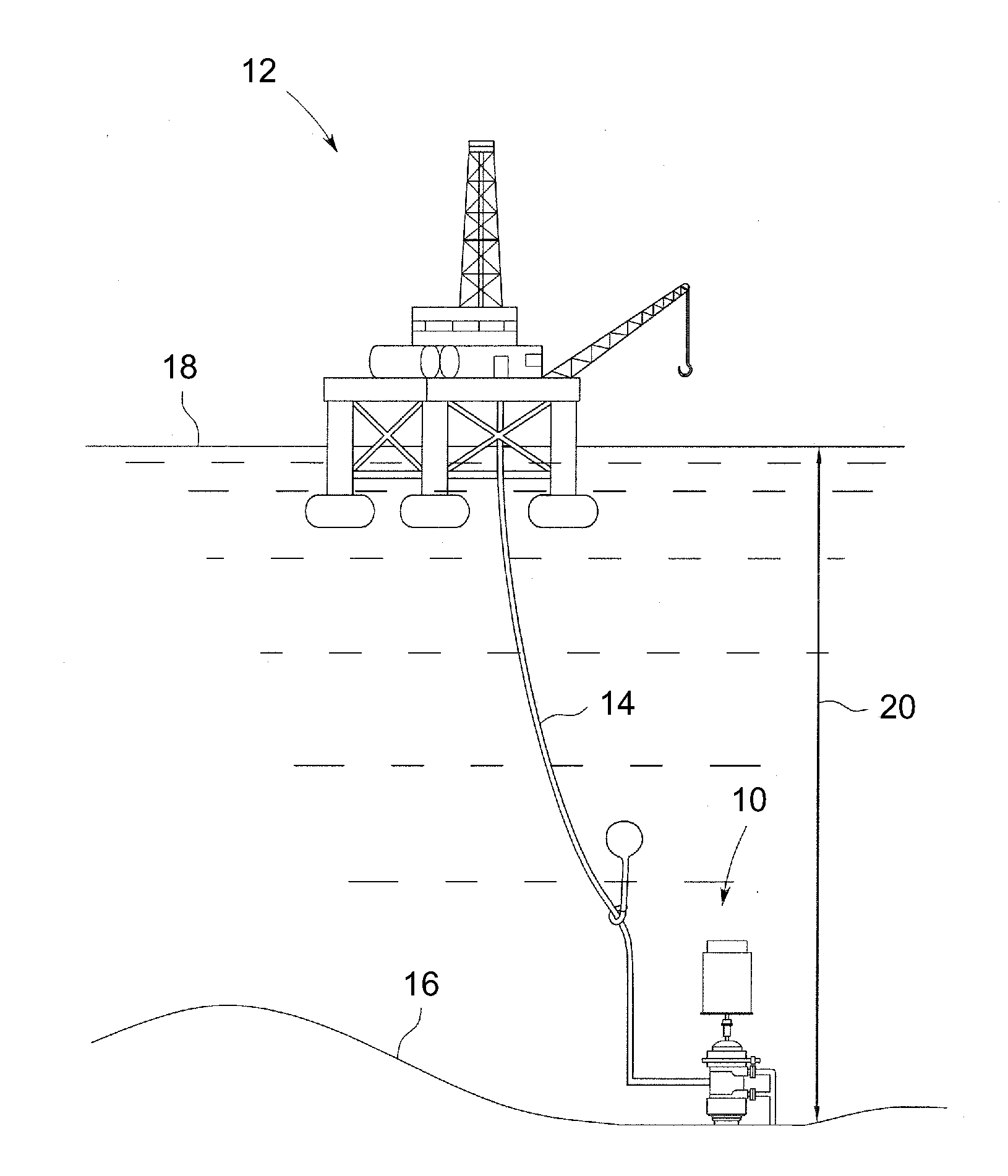
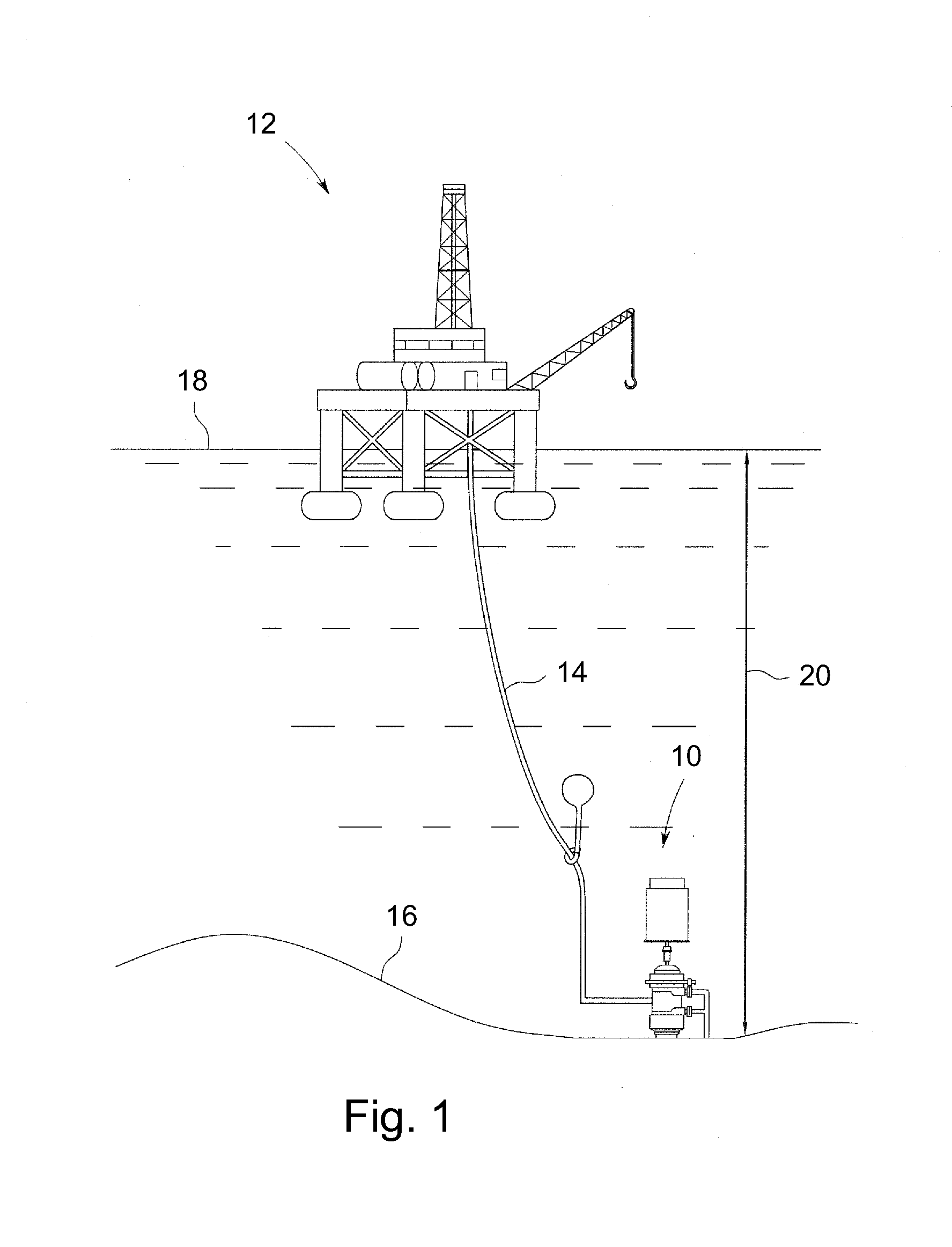
[0020]FIG. 1 is a schematic diagram of a screw pump system 10 that may be provided with a production platform 12 to pump a fluid for processing, storage and / or transport. As depicted, the screw pump system 10 may be connected to the production platform 12 via a conduit or riser 14 that may be used to route a process fluid to the ...


PUM

PropertyMeasurementUnit
angleaaaaaaaaaa
thicknessesaaaaaaaaaa
weightaaaaaaaaaa

Abstract

A subsea system includes a multiphase pump, configured to transfer a multiphase fluid and a multiphase separator, configured to separate the multiphase fluid into solid, liquid, and gaseous phases. The multiphase separator includes a solid-liquid separation device, which is configured to facilitate separation of the solid phase and the liquid phase from the multiphase fluid. The multiphase separator includes a gas-liquid separation device, which is configured to facilitate separation of the gaseous phase and the liquid phase from the multiphase fluid. The multiphase separator includes a liquid reservoir, which is configured to contain a volume of the liquid phase to be used as a lubricant for the multiphase pump. Finally, the multiphase separator includes a liquid outlet, which is configured to transfer the liquid phase from the liquid reservoir to the multiphase pump.

Description

BACKGROUND OF THE INVENTION[0001]The subject matter disclosed herein relates to a screw pump, and more particularly to the lubrication of a multiphase screw pump.[0002]Screw pumps are rotary, positive displacement pumps that use two or more screws to transfer high or low viscosity fluids or fluid mixtures along an axis. A twin screw pump typically has two intermeshing counter-rotating rotor screws. The volumes or cavities between the intermeshing screws and a liner or casing transport a specific volume of fluid in an axial direction around threads of the screws. As the screws rotate, the fluid volumes are transported from an inlet to an outlet of the pump. In some applications, twin screw pumps are used to aid in the extraction of oil and gas from on-shore and subsea wells.[0003]In many cases, a twin screw pump may be used to pump a multiphase fluid from a subsea well, which may be processed to produce petroleum products. Accordingly, twin screw pumps may be configured to prevent th...

Claims


Application Information

Patent Timeline
Patent Type & Authority Applications(United States)
IPC IPC(8): B01D35/02B01D19/00
CPCF04C13/008F04C15/0088F04C2210/24F04D13/10F04D29/063B01D21/267B01D21/0018B01D21/0045B01D21/245B01D21/2494F16N39/00B01D21/0006B01D21/0021B01D21/2411B01D21/30B01D21/34
Inventor ANDERSON, DAVID DELOYDKOTHNUR, VASANTH SRINIVASADEO, HRISHIKESH VISHVASSVEEN, JOHAN KRISTIANSAELE, OVE
Owner VETCO GRAY SCANDINAVIA
Learn More