Lighting apparatus
a technology of lighting apparatus and light source, which is applied in the direction of lighting and heating apparatus, lighting source combinations, instruments, etc., can solve the problems of further examination and achieve the effect of easy control
- Summary
- Abstract
- Description
- Claims
- Application Information
AI Technical Summary
Benefits of technology
Problems solved by technology
Method used
Image
Examples
embodiment 1
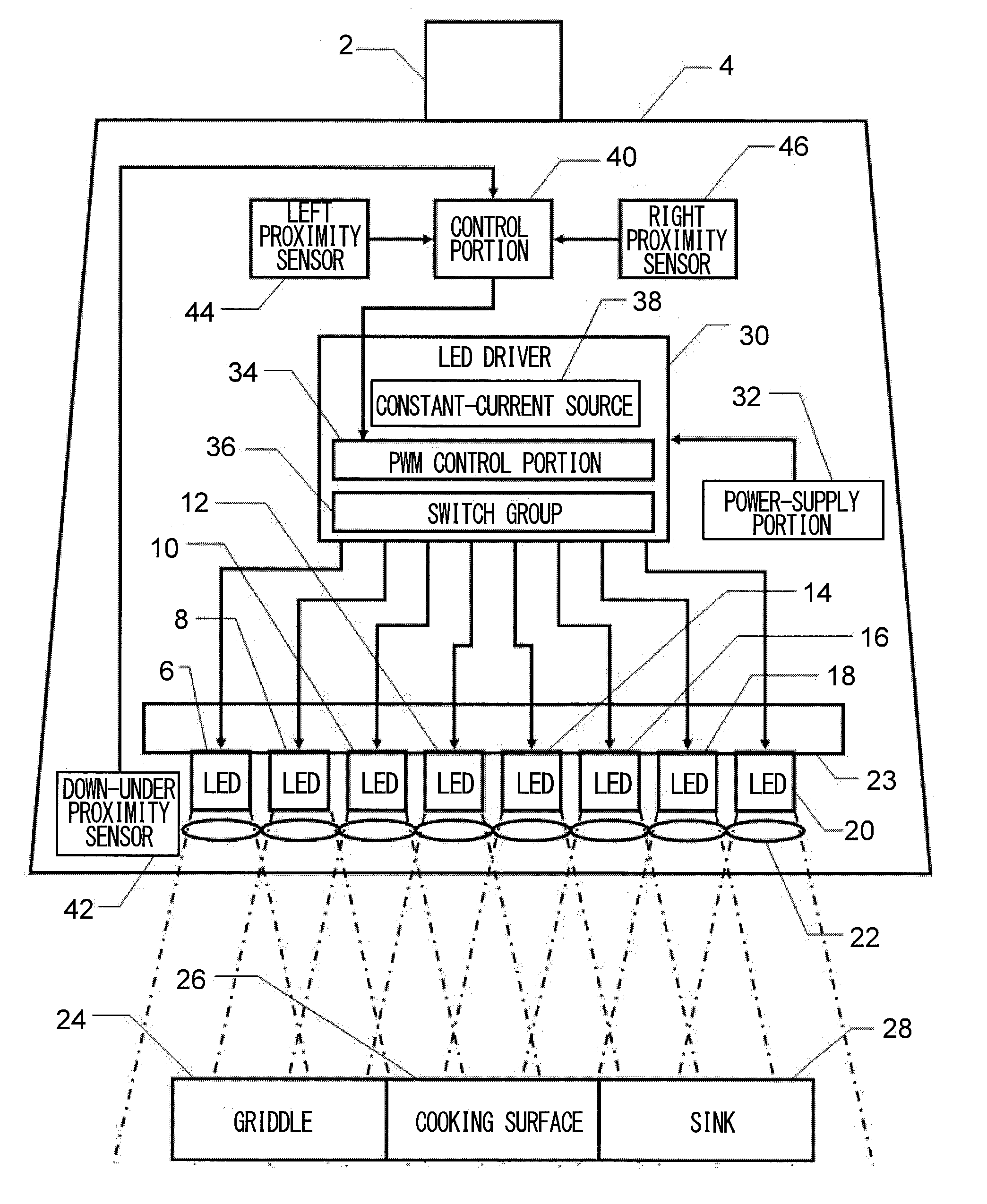
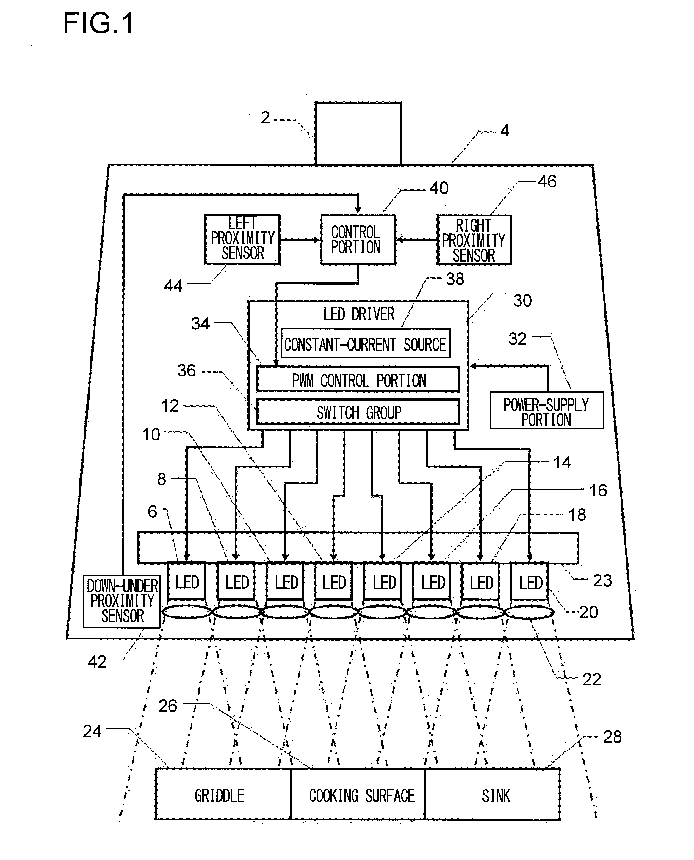
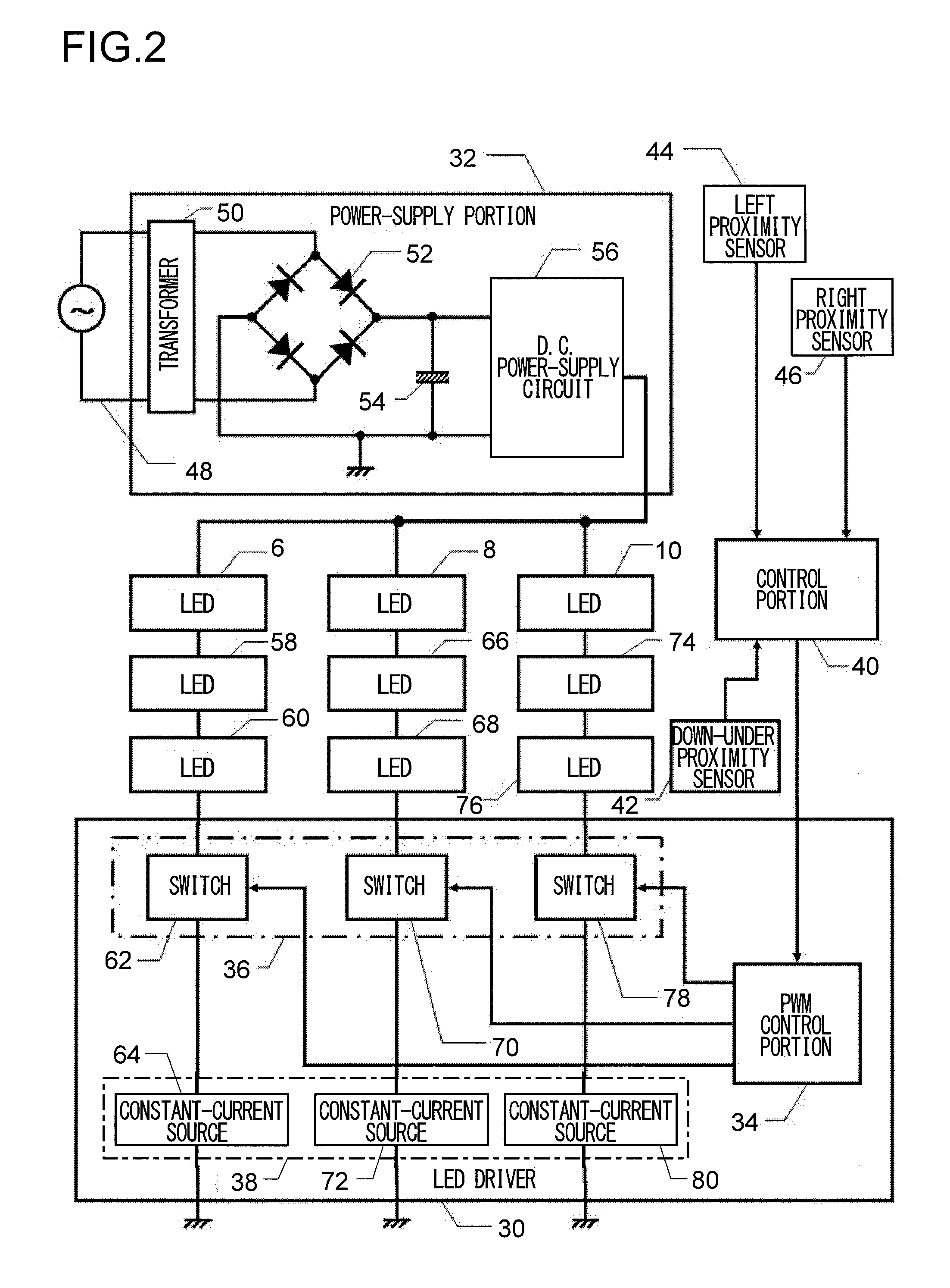
[0029]FIG. 1 is a block diagram of a lighting apparatus according to Embodiment 1 of the present invention. Embodiment 1 is formed as a kitchen cooking area lighting apparatus 4 that is fixed at a suitable upper position of a kitchen by a hold portion 2. Here, the block diagram in FIG. 1 is schematically illustrated for convenience of the understanding; however, if description of an actual structure is necessary, the description is suitably supplemented hereinafter. The lighting apparatus 4 has a plurality of white light emitting diodes (LED) 6, 8, 10, 12, 14, 16, 18 and 20; collects white light, emitted into a relatively wide angle from the diodes, by means of small lens groups of a light collection lens array 22 that is disposed on a front surface; and radiates the light downward. Besides, each white light LED is in thermal contact with a heat radiation plate 23 that is formed of a metal; and prevents deterioration of the light emission efficiency by means of cooling by the heat r...
embodiment 2
[0049]FIG. 6 is a block diagram of a lighting apparatus according to Embodiment 2 of the present invention. Embodiment 2 also is formed as a kitchen cooking area lighting apparatus 104 that is fixed at a suitable upper position of a kitchen by a hold portion 102. Besides, because most of the structure is common to Embodiment 1, the common portions are indicated by reference numbers on the order of 100 with the common second and first digits and description is skipped unless necessary. Besides, the detailed structures shown in FIG. 2 to FIG. 5 are also applicable to Embodiment 2 and other embodiments that are described hereinafter. What Embodiment 2 in FIG. 6 is different from Embodiment 1 in FIG. 1 is a point that white light LEDs 106 to 120 are disposed on an inward bent surface and the light collection lens array 22 disposed in Embodiment 1 is omitted. Because of this, a heat radiation plate 123 also has an inward bent shape.
[0050]As a result of the above structure, even without t...
embodiment 3
[0053]FIG. 8 is a block diagram of a lighting apparatus according to Embodiment 3 of the present invention. Embodiment 3 also is formed as a kitchen cooking area lighting apparatus 204 that is fixed at a suitable upper position of a kitchen by a hold portion 202. Besides, because most of the structure is common to Embodiment 1 and Embodiment 2, the common portions are indicated by reference numbers on the order of 200 with the common second and first digits and description is skipped unless necessary. A first point in which Embodiment 3 in FIG. 8 is different from Embodiment 1 in FIG. 1 or e Embodiment 2 in FIG. 6 is that white light LEDs 208, 212, 216, 220 and the like are evenly mingled with yellow light LEDs 207, 209, 211, 213 and the like.
[0054]And, the white light LEDs 208, 212, 216, 220 and the like are controlled by a white light LED driver 230 that is supplied with electricity by a white light power supply portion 232; independent of this, the yellow light LEDs 207, 209, 211...
PUM
 Abstract
Description
Claims
Application Information
 - R&D
- Intellectual Property
- Life Sciences
- Materials
- Tech Scout
- Unparalleled Data Quality
- Higher Quality Content
- 60% Fewer Hallucinations
Browse by: Latest US Patents, China's latest patents, Technical Efficacy Thesaurus, Application Domain, Technology Topic, Popular Technical Reports.
© 2025 PatSnap. All rights reserved.Legal|Privacy policy|Modern Slavery Act Transparency Statement|Sitemap|About US| Contact US: help@patsnap.com


