Feedback System for Identifying Movement and Intensity of External Force
a technology of external force and feedback system, which is applied in the field of feedback system, can solve the problems of insufficient processing of graphics, restricting usage, and not being suitable for small mobile equipment us
- Summary
- Abstract
- Description
- Claims
- Application Information
AI Technical Summary
Problems solved by technology
Method used
Image
Examples
first embodiment
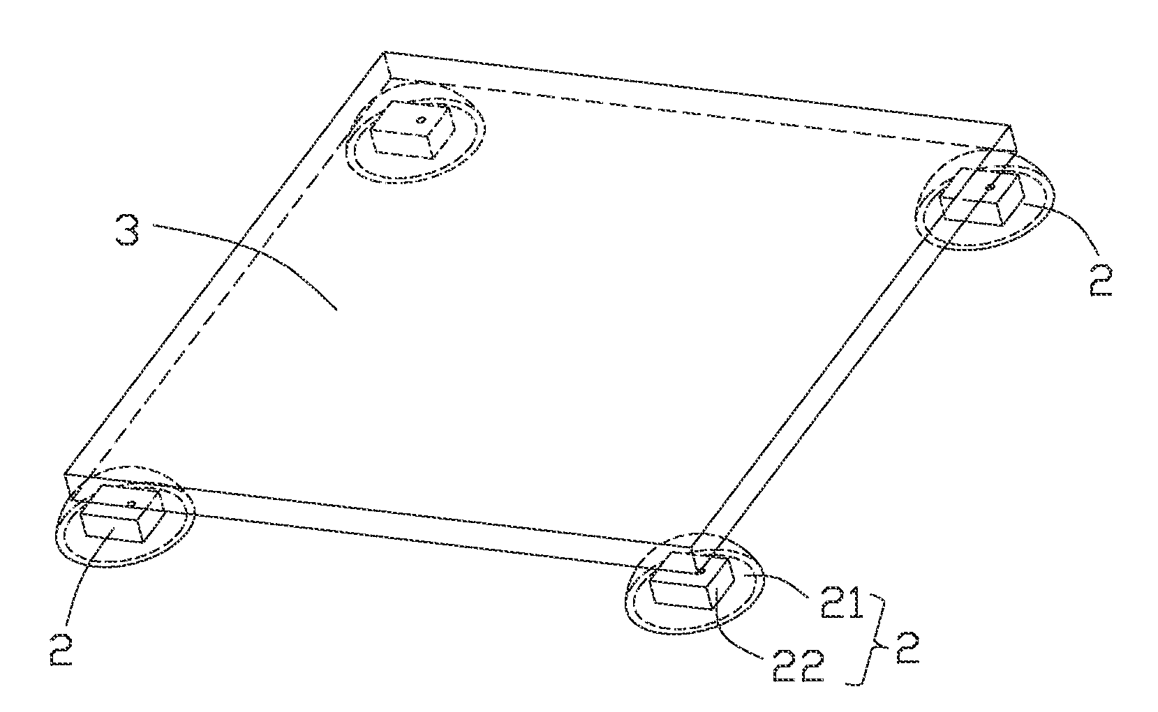
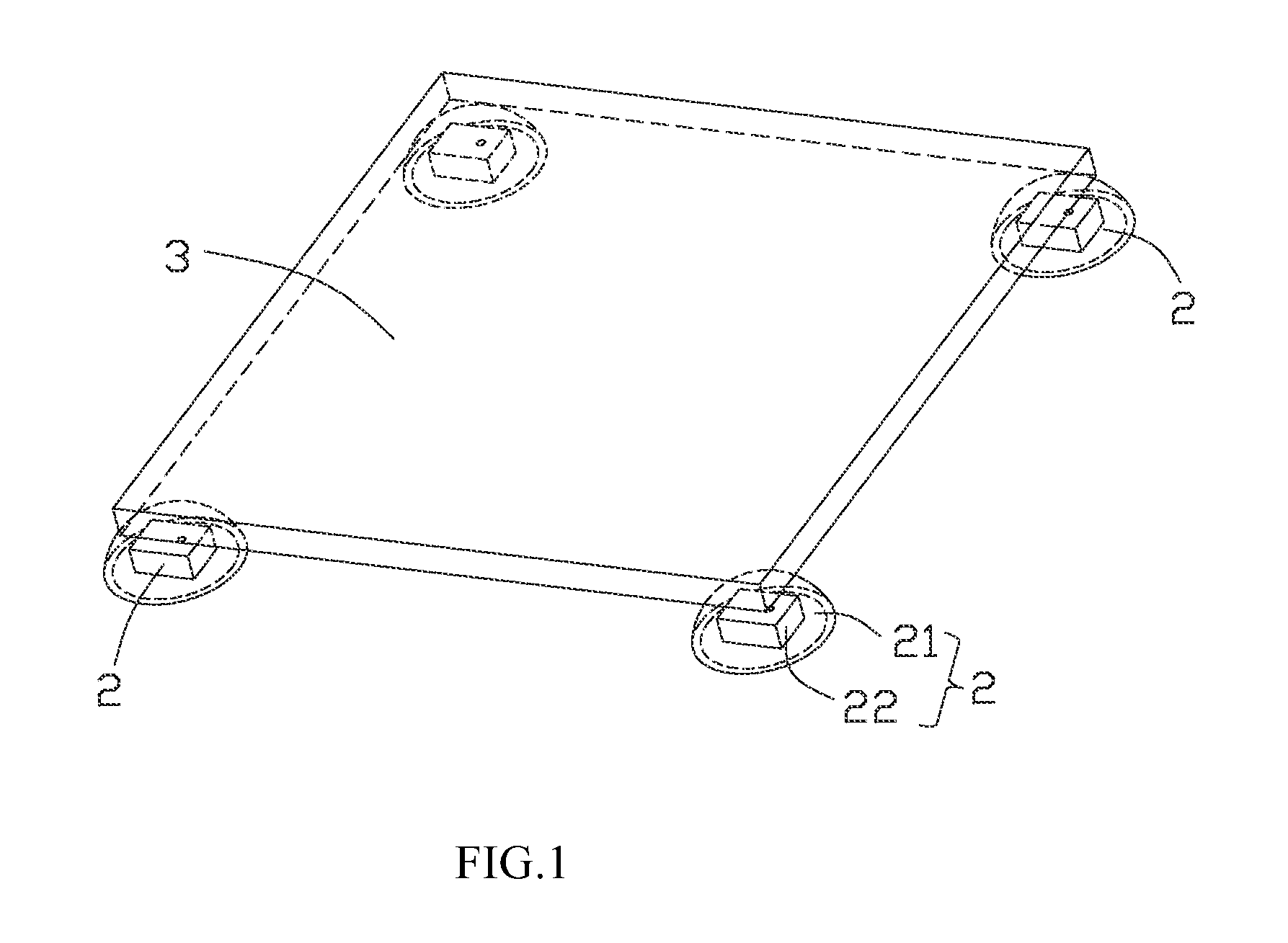
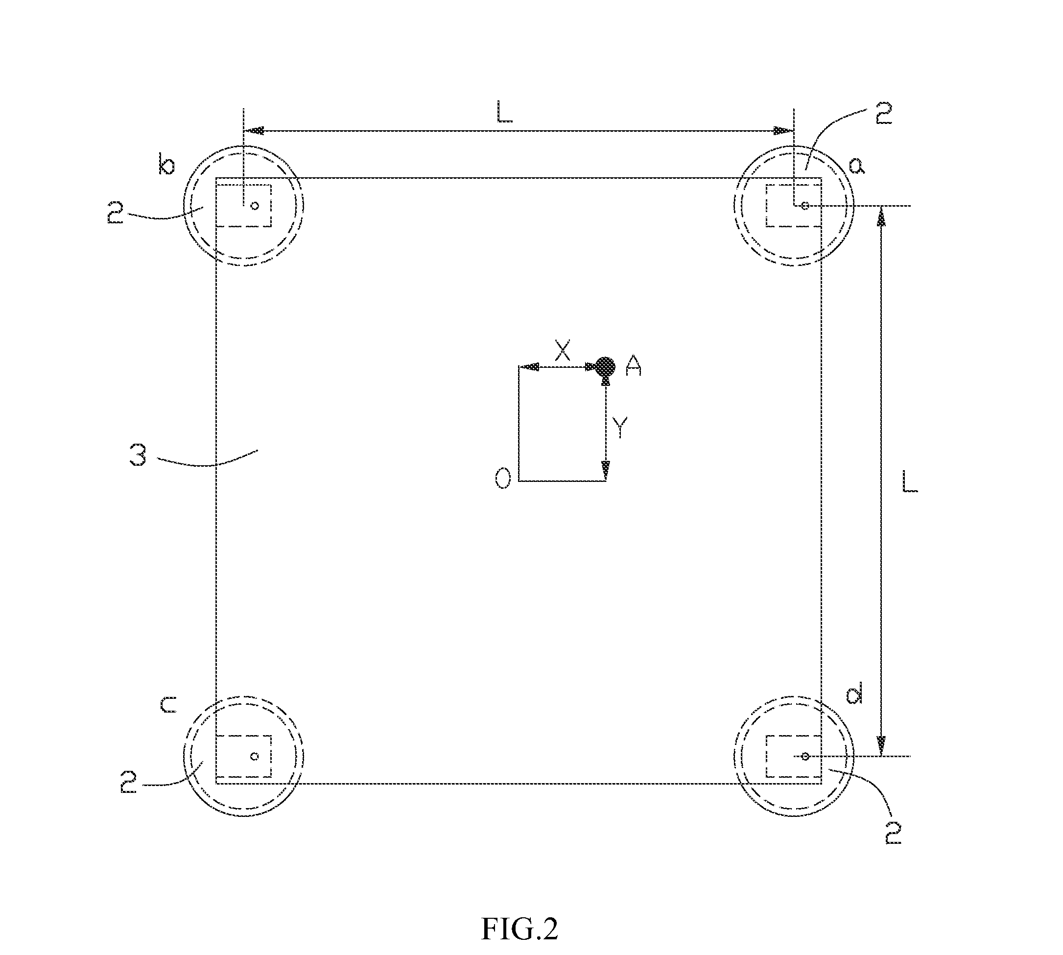
[0027]FIGS. 1-3 illustrate a feedback system 100 for identifying movement and intensity of an external force. The feedback system 100 includes a flat support plate 1, a plurality of pressure-sensing units 2 mounted on the support plate 1, an operation plate 3 upwardly supported by the pressure-sensing units 2, and a receiving block 4 fastened to the support plate 1 for restricting upward movement of the operation plate 3 to avoid disassembly of the operation plate 3 and the receiving block 4. Referring to FIGS. 2, 4&5, each pressure-sensing unit 2 includes a half-ball shaped elastic member 21 and a pressure sensor 22. The elastic member 21 is hollow in order to receive the pressure sensor 22. An inner side of the elastic member 21 is filled with fluid material surrounding the pressure sensor 22. The fluid material is gas or liquid or glue etc. According to the preferred embodiment of the present invention, the fluid material is air for lower costs. The pressure sensor 22 includes a ...
second embodiment
[0035]Referring to FIGS. 11 and 12, another feedback system 200 for identifying movement and intensity of an external force is disclosed. The feedback system 200 is similar to the feedback system 100 of the first embodiment. The differences between them are that the feedback system 200 includes an unique operation plate 5 which comprises a plate portion 51 supported by the elastic members 21, an operating handle 52 upwardly extending from the plate portion 51, and a support lever 53 extending downwardly from the plate portion 51. The limiting stopper 42 is located over the plate portion 51 in order to restrict upward movement of the plate portion 51 to avoid disassembly thereof. The operating handle 52 is integrally formed with the plate portion 51 and extends upwardly beyond the limiting stopper 42 through the opening 43 for being driven by a finger. The support lever 53 abuts against the support plate 1. The plate portion 51 and the support lever 53 are made of flexible materials ...
third embodiment
[0038]Referring to FIGS. 14 to 16, another feedback system 300 for identifying movement and intensity of an external force is disclosed. The feedback system 300 is similar to the feedback system 200 of the second embodiment. The differences between them are the structure of the operation plate and the elastic member. The feedback system 300 includes an unique operation plate 6 which comprises a plate portion 61 supported by a plurality of pressure-sensing units 2, and an operating handle 62 upwardly extending from the plate portion 61. The operating handle 62 functions of transmitting the pressure force of the finger to the pressure-sensing units 2. The elastic members 21 function of converting the pressure force into fluid pressure which is identified by the pressure sensors 22. Each elastic member 21 of the pressure-sensing units 2 includes an upstanding corrugated tub with different diameters. The corrugated tub is center hollow in order to receive the pressure sensor 22, and the...
PUM
| Property | Measurement | Unit |
|---|---|---|
| pressure sensitive | aaaaa | aaaaa |
| pressure | aaaaa | aaaaa |
| diameters | aaaaa | aaaaa |
Abstract
Description
Claims
Application Information
 - R&D Engineer
- R&D Manager
- IP Professional
- Industry Leading Data Capabilities
- Powerful AI technology
- Patent DNA Extraction
Browse by: Latest US Patents, China's latest patents, Technical Efficacy Thesaurus, Application Domain, Technology Topic, Popular Technical Reports.
© 2024 PatSnap. All rights reserved.Legal|Privacy policy|Modern Slavery Act Transparency Statement|Sitemap|About US| Contact US: help@patsnap.com


