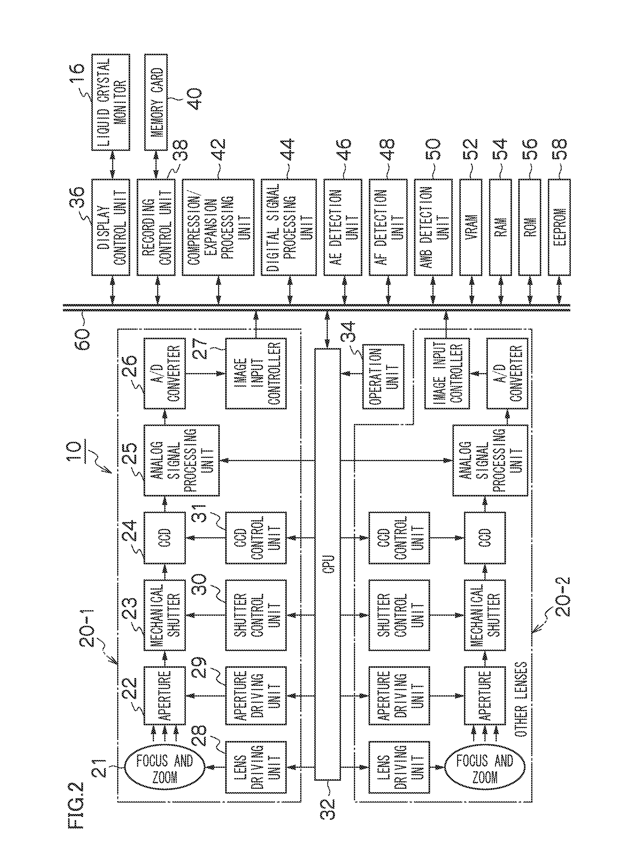
Stereoscopic imaging apparatus
a technology of stereoscopic imaging and optical equipment, which is applied in the direction of instruments, television systems, focusing aids, etc., can solve the problems of difficult mechanical adjustment of optical axes, deviating optical axes and individual differences of two imaging optical systems
- Summary
- Abstract
- Description
- Claims
- Application Information
AI Technical Summary
Benefits of technology
Problems solved by technology
Method used
Image
Examples
third embodiment
[Third Embodiment of Image Processing in Continuous Photographing]
[0176]FIG. 18 is a flow chart showing a third embodiment of the image processing in the continuous photographing. Common parts with the first embodiment of the image processing in the continuous photographing shown in FIG. 16 are designated with the same step numbers, and the detailed description will not be repeated.
[0177]The third embodiment of the image processing in the continuous photographing shown in FIG. 18 is different from the first embodiment in that only images, for which the storage is instructed by the user, among a plurality of continuously photographed time-series images are stored in the memory card 40.
[0178]In FIG. 18, when the switch S2 is turned OFF (step S116), the time-series left and right images stored in the RAM 54 are read out and reproduced in the order of photographing (step S130).
[0179]Now, when photographing of 3D images is performed N times by continuous photographing, N-th left and righ...
first embodiment
[First Embodiment of Imaging / Reproduction Process]
[0183]FIGS. 19 and 20 are flow charts showing a first embodiment of an photographing / reproduction process of the stereoscopic imaging apparatus 10 according to the present invention.
[0184]In FIG. 19, when the stereoscopic imaging apparatus 10 is set to the photographing mode to start photographing, the photographing mode at the time of photographing (for example, 3D moving image photographing mode or 3D still image photographing mode), the zoom position of the zoom lenses, and the amounts of optical axis deviation are written in a tag of an image file recorded in the memory card 40 (step S140). The amounts of optical axis deviation is read out from the EEPROM 48 or calculated based on the photographing mode, the zoom position, and the focus position.
[0185]Photographed left and right images of full angle of view (moving image or still images) are stored in the image file (step S142).
[0186]Therefore, the distortion correction and the c...
second embodiment
[Second Embodiment of Photographing / Reproduction Process]
[0194]FIGS. 21 and 22 are flow charts showing a second embodiment of the photographing / reproduction process of the stereoscopic imaging apparatus 10 according to the present invention.
[0195]In FIG. 21, when the stereoscopic imaging apparatus 10 is set to the photographing mode to start photographing, various correction processes are applied to the photographed left and right images of full angle of view (moving image or still images) (step S160). The image processing here is image processing other than the cut-out process of image for correcting the optical axis deviation of the left and right images, and the image processing includes white balance correction, gamma correction, shading correction, distortion correction, and the like.
[0196]The left and right images subjected to the image processing are compressed in a predetermined compression format and stored in the memory card 40 (step S162).
[0197]Meanwhile, as shown in FIG....
PUM
 Abstract
Description
Claims
Application Information
 - R&D
- Intellectual Property
- Life Sciences
- Materials
- Tech Scout
- Unparalleled Data Quality
- Higher Quality Content
- 60% Fewer Hallucinations
Browse by: Latest US Patents, China's latest patents, Technical Efficacy Thesaurus, Application Domain, Technology Topic, Popular Technical Reports.
© 2025 PatSnap. All rights reserved.Legal|Privacy policy|Modern Slavery Act Transparency Statement|Sitemap|About US| Contact US: help@patsnap.com


