
Airflow generator

a generator and airflow technology, applied in the direction of electric generator control, wind motor with solar radiation, machines/engines, etc., can solve the problems of shrinking natural resources and aging of existing infrastructure, and achieve the effect of facilitating the rotation of the turbine blade assembly

Inactive Publication Date: 2012-02-16
US GREEN ENERGY SOLUTIONS
View PDF3 Cites 49 Cited by
  • Summary
  • Abstract
  • Description
  • Claims
  • Application Information

AI Technical Summary

Benefits of technology

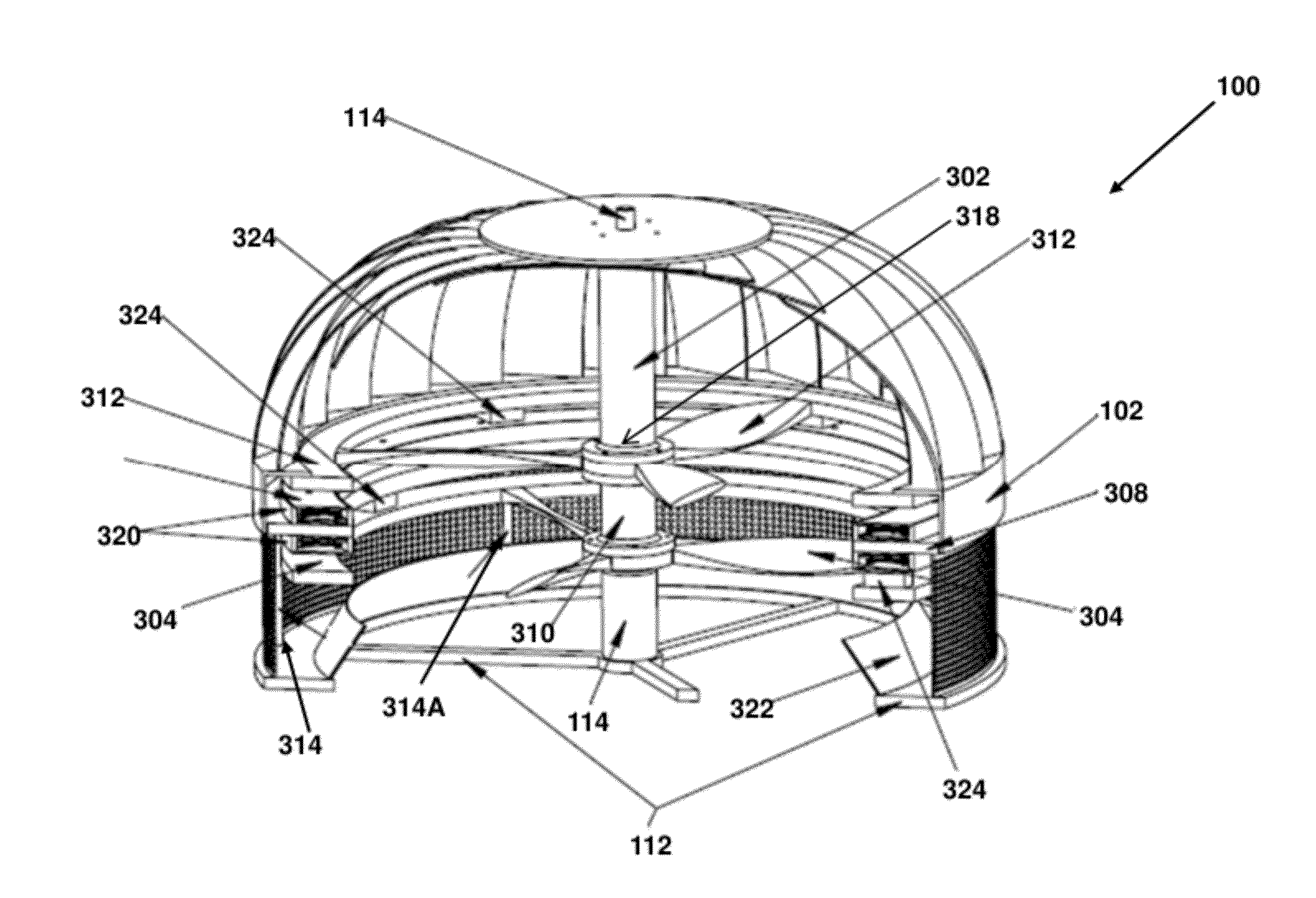
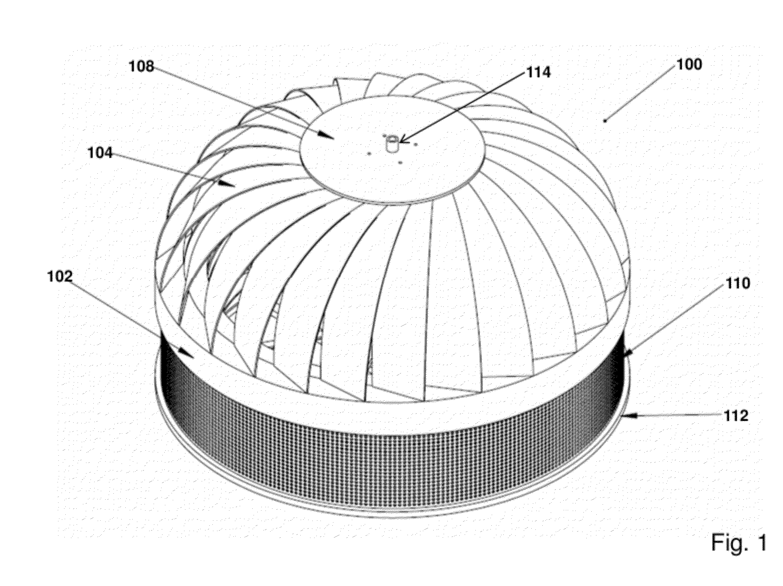
[0058]In another embodiment, methods and systems described herein provide an airflow generator that may be configured to convert air flow into electricity. The airflow generator may include a stationary drive shaft that may be configured to facilitate rotation of a turbine blade assembly. The turbine blade assembly may include a plurality of permanent magnets disposed along a circular circumference. The airflow generator may also include a plurality of stator coils disposed on a stationary surface. The plurality of stator coils may be disposed in close proximity to the plurality of permanent magnets. Further, the plurality of stator coils may be disposed on a co-planer axis spaced outwardly from the stationary axis shaft. In an embodiment, a rotating motion of the plurality of permanent magnets may form a plane that may be substantially parallel to the plurality of stator coils.

Problems solved by technology

As the demand for energy continues to rise, the existing infrastructure continues to age and our natural resources continue to shrink.
Energy inefficiency and emissions associated with the heating, cooling, and operation of commercial, industrial, institutional and residential buildings have an increasing impact on the environment.

Method used


Image

  • Airflow generator
  • Airflow generator
  • Airflow generator

Examples


Embodiment Construction

)

[0086]Detailed embodiments are disclosed herein; however, it is to be understood that the disclosed embodiments are merely, which may be embodied in various forms. Therefore, specific structural and functional details disclosed herein are not to be interpreted as limiting, but merely as a basis for the claims and as a representative basis for teaching one skilled in the art to variously employ an airflow generator in virtually any appropriately detailed structure. Further, the terms and phrases used herein are not intended to be limiting, but rather to provide an understandable description.

[0087]The terms “a” or “an,” as used herein, are defined as one or more than one. The term “another,” as used herein, is defined as at least a second or more. The terms “including” and / or “having”, as used herein, are defined as comprising (i.e., open transition). The term “coupled” or “operatively coupled,” as used herein, is defined as connected, although not necessarily directly and / or mechani...


PUM


Abstract

Converting an air flow into a source of electricity by an airflow generator includes disposing the airflow generator in an air flow path of a machine for receiving the air flow to rotate a turbine bladed portion of the airflow generator that causes a plurality of permanent magnets disposed along the circumference of the bladed portion to cyclically move in close proximity to a plurality of fixed position stator coils thereby generating electrical currents in the coils that can be harvested.

Description

CROSS-REFERENCE TO RELATED APPLICATIONS[0001]This application claims the benefit of provisional application U.S. Ser. No. 61 / 372,172 filed Aug. 10, 2010 which is hereby incorporated by reference in its entirety.BACKGROUND[0002]1. Field[0003]An airflow generator is in the technical field of Renewable Energy Devices, more particularly, an airflow generator is in the technical field of generating electricity from a turbine using natural or manmade air flow sources.[0004]2. Description of the Related Art[0005]As the demand for energy continues to rise, the existing infrastructure continues to age and our natural resources continue to shrink. Energy inefficiency and emissions associated with the heating, cooling, and operation of commercial, industrial, institutional and residential buildings have an increasing impact on the environment. Air flow associated with systems that have an increasing impact on the environment generally provide little secondary benefit, yet there is a potential ...

Claims


Application Information

Patent Timeline
Patent Type & Authority Applications(United States)
IPC IPC(8): H02K7/18
CPCF05B2220/602F03D9/34H02K3/47H02K7/183H02K11/046H02K21/24Y02E10/725F03D9/00F05B2220/62F03D7/026Y02B10/30Y02E10/728B60L8/006F03D9/007F03D9/25F03D9/32F05B2240/215Y02E10/72Y02T10/64Y02T10/7072H02K11/049
Inventor SMITH, JR., EDGAR A.SMITH, PATRICK S.
Owner US GREEN ENERGY SOLUTIONS
Learn More