Supplying power to underwater devices

a technology for underwater devices and electrical power, applied in the direction of inductances, sealing/packing, borehole/well accessories, etc., can solve the problems of high cost of wiring, high barometric pressure and low temperature, and achieve the effect of reducing the need for expensive wiring

Inactive Publication Date: 2012-02-09
GE OIL & GAS UK LTD
View PDF5 Cites 9 Cited by
  • Summary
  • Abstract
  • Description
  • Claims
  • Application Information

AI Technical Summary

Benefits of technology

[0014]The invention reduces the need for expensive wiring and feed through connectors between devices in an SCM and external devices requiring power to operate.

Problems solved by technology

However, the wiring, along with the connectors which have to operate under high barometric pressures and low temperatures, are expensive.

Method used


Image

  • Supplying power to underwater devices
  • Supplying power to underwater devices
  • Supplying power to underwater devices

Examples


Embodiment Construction

[0020]The concept of transmitting electric power by magnetic resonance is as old as the discovery of electricity in that Tesla himself proposed the technique. In practice, the technique has had no place in electrical engineering technology until recent times, mainly because the cheap electronics required to achieve power transfer by magnetic resonance have only recently become available.

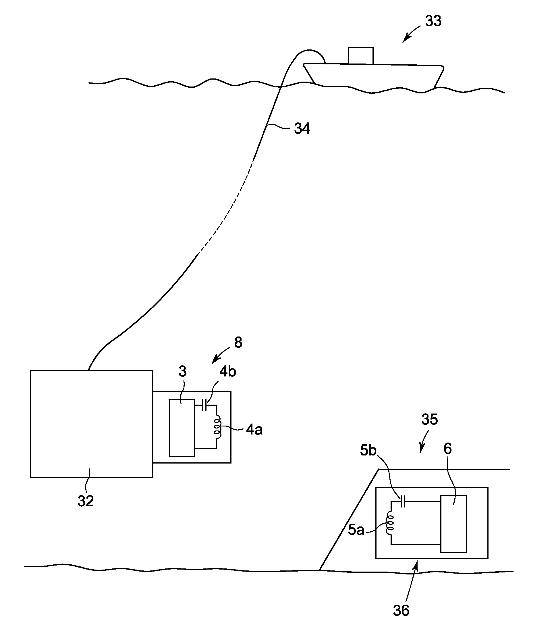
[0021]The basic principle of magnetic resonance involves a transformer where the core is not a ferrous material but air (or a vacuum). Within the transformer, the primary and secondary windings are resonant at the operating frequency of the primary current supplied from a source. The high ‘magnetic gain’ i.e. ‘High Q’ of the resonant secondary winding allows it to be separated from the primary winding by several metres, thus resulting in power transmission wirelessly.

[0022]The technique has been recently demonstrated by the company Witricity to charge laptop and mobile phone batteries without a wired...


PUM

PropertyMeasurementUnit
frequencyaaaaaaaaaa
electrical poweraaaaaaaaaa
poweraaaaaaaaaa

Abstract

A method of supplying electrical power to at least one device at a tree of an underwater fluid extraction well is disclosed. The method comprises using magnetic resonance coupling for wirelessly transmitting power from a supply to each device.

Description

BACKGROUND OF THE INVENTION[0001]1. Field of the Invention[0002]Embodiments of the present invention relate to the supply of electrical power to underwater devices, in particular those at a tree of an underwater fluid extraction well.[0003]2. Description of the Prior Art[0004]On a subsea fluid extraction well Christmas tree, the supply of electrical power to pressure and / or temperature (P / T) sensors and to directional control valves (DCVs) within a subsea control module (SCM) is typically supplied. from a subsea electronics module (SEM). Likewise, electrical power to sensors mounted on the Christmas tree itself, external to the SCM, are also fed from the SEM via the SCM. Such power is supplied via simple wiring. However, the wiring, along with the connectors which have to operate under high barometric pressures and low temperatures, are expensive. Embodiments of the present invention provide a cheaper alternative to the power wiring and connectors.BRIEF SUMMARY OF THE INVENTION[0005...

Claims


Application Information

Patent Timeline
Patent Type & Authority Applications(United States)
IPC IPC(8): H02J17/00H01F38/14
CPCE21B33/0355H02J5/005H01F38/14H02J50/80H02J50/12H02J50/40E21B41/0085
Inventor OVERTON, PAULPACKHAM, ANDREW ROBERT
Owner GE OIL & GAS UK LTD
Why Eureka
Try Eureka