Equalizing unit of a drive train of a motor vehicle and its construction for loss-minimizing oiling on demand

Active Publication Date: 2012-02-09
GKN DRIVELINE KOPING
View PDF2 Cites 36 Cited by
  • Summary
  • Abstract
  • Description
  • Claims
  • Application Information

AI Technical Summary

Benefits of technology

[0010]The arrangement of the oil delivery wheel distant from the clutch device results in that the oil following a passage through the clutch device to be oiled always flows back into the oil sump of the equalizing unit before it is again fed into the oil circuit. Thus, adequate mixing-through of the entire oil volume and consequently the utilization of the maximum cooling output of the total oil quantity is guaranteed at all times, which in turn reduces thermal loading of the clutch devices.
[0012]The mentioned configuration additionally makes possible designing the oil delivery wheel in such a manner that it is able to deliver the cooling and lubricating oil from an oil sump with an oil level located below the clutch device. The clutch device, that is particularly also the dragged clutch components, can thus be permanently located above the oil level. Even the outer disc carrier located radially outside and the outer discs do not cause any splashing losses either under load, that is for example with connected secondary part of the drive train, nor in the opened mode, that is with disconnected secondary part.
[0015]In order to increase the oil flow, at least part-circumferential bulkheads can be provided which minimize the lateral outflow of the oil taken along by the oil delivery wheel.
[0018]In order to interrupt this equilibrium a braking or decoupling device is provided, by means of which the oil delivery wheel can be stopped when there is no oiling need for the clutch device. With such a braking or decoupling device the state of equilibrium which would otherwise materialize can be effectively prevented for the braking or decoupling device brings about that—depending on where and how the braking or decoupling device intervenes—the drag power can no longer be transmitted from the one clutch side to the other clutch side since the former is already braked and / or since through the decoupling of the oil delivery wheel from its drive member the drag power is not transmitted to the oil delivery wheel. However, as soon as the oil delivery wheel is stationary the oil flow is interrupted and the undesired oiling in the drag state is terminated. The clutch device briskly runs dry and the two clutch sides rotate with significantly lower loss.

Problems solved by technology

The disproportionate heating of the clutch brings disadvantages with regard to the wear characteristics and thus the lifespan and also with regard to the response and control behavior.
A further disadvantage of the embodiment shown in DE 10 2008 002 844 A1 is that the clutch packages of the side shaft clutches stand in the oil in order to collect it and deliver it to the oil collection pocket.
The concomitant splashing losses increase the dissipation of the drive train.
However, as soon as these start to rotate these in turn deliver oil into the previously described internal oil circuit and on their part thus again increase the delivered oil volume and thus the friction loss or dissipation.
In addition, the low-friction surfaces of the inner discs result in a significantly poorer response and control behavior of the clutch package.
A disadvantage, which weighs heavier than the advantages that can be achieved with the dissipation through these measures.

Method used


Image

  • Equalizing unit of a drive train of a motor vehicle and its construction for loss-minimizing oiling on demand
  • Equalizing unit of a drive train of a motor vehicle and its construction for loss-minimizing oiling on demand
  • Equalizing unit of a drive train of a motor vehicle and its construction for loss-minimizing oiling on demand

Examples


Embodiment Construction

[0008]Before this background it is the object of the invention to make available an equalizing unit of the type mentioned at the outset, with which the disadvantages described above are avoided. In particular, the oiling concept described in DE 10 2008 002 844 A1 is to be optimized with regard to the dissipation caused by this upon a secondary part decoupled from the primary part of the drive train without having to accept compromises with the response and control behavior of the clutch packages.

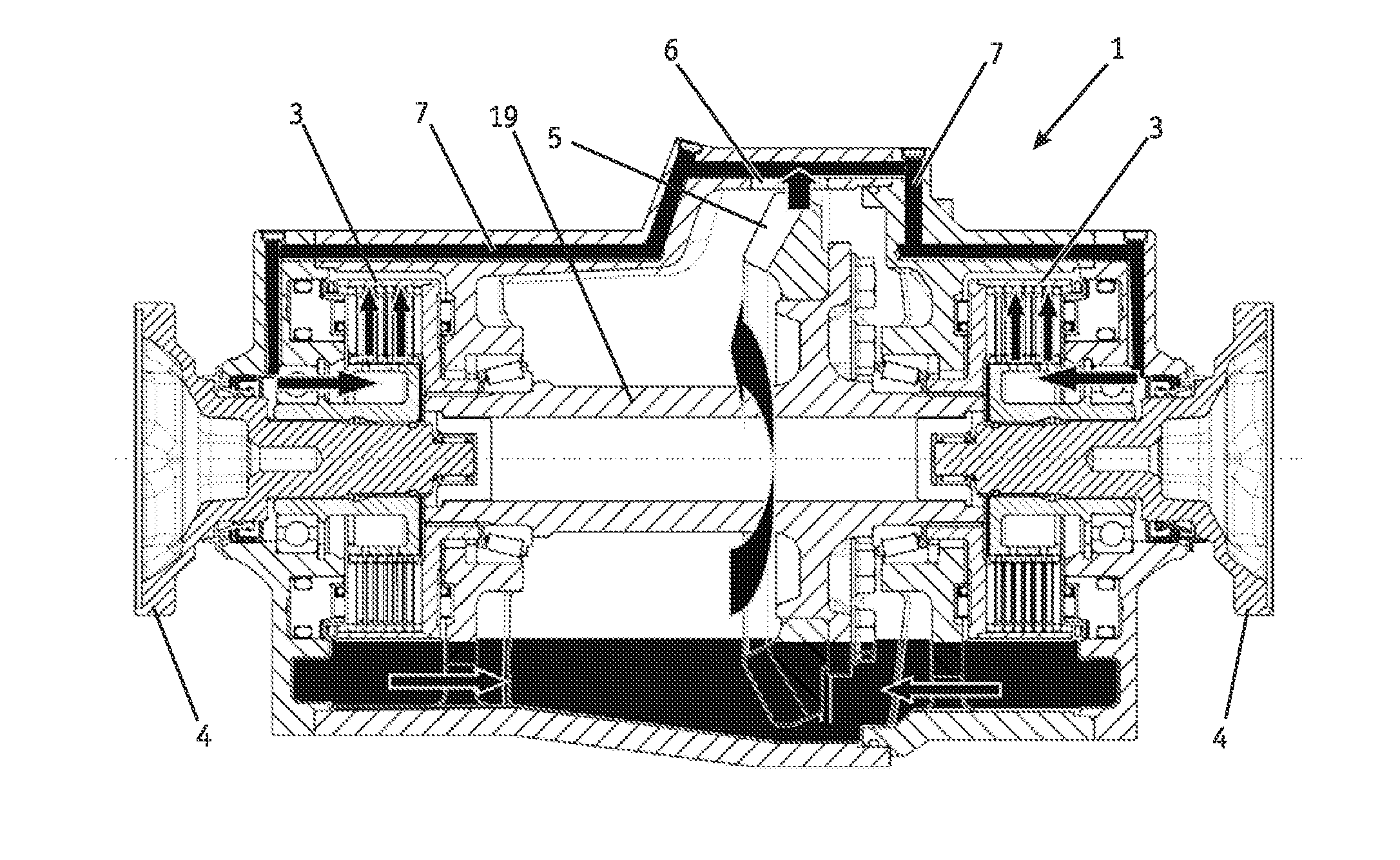
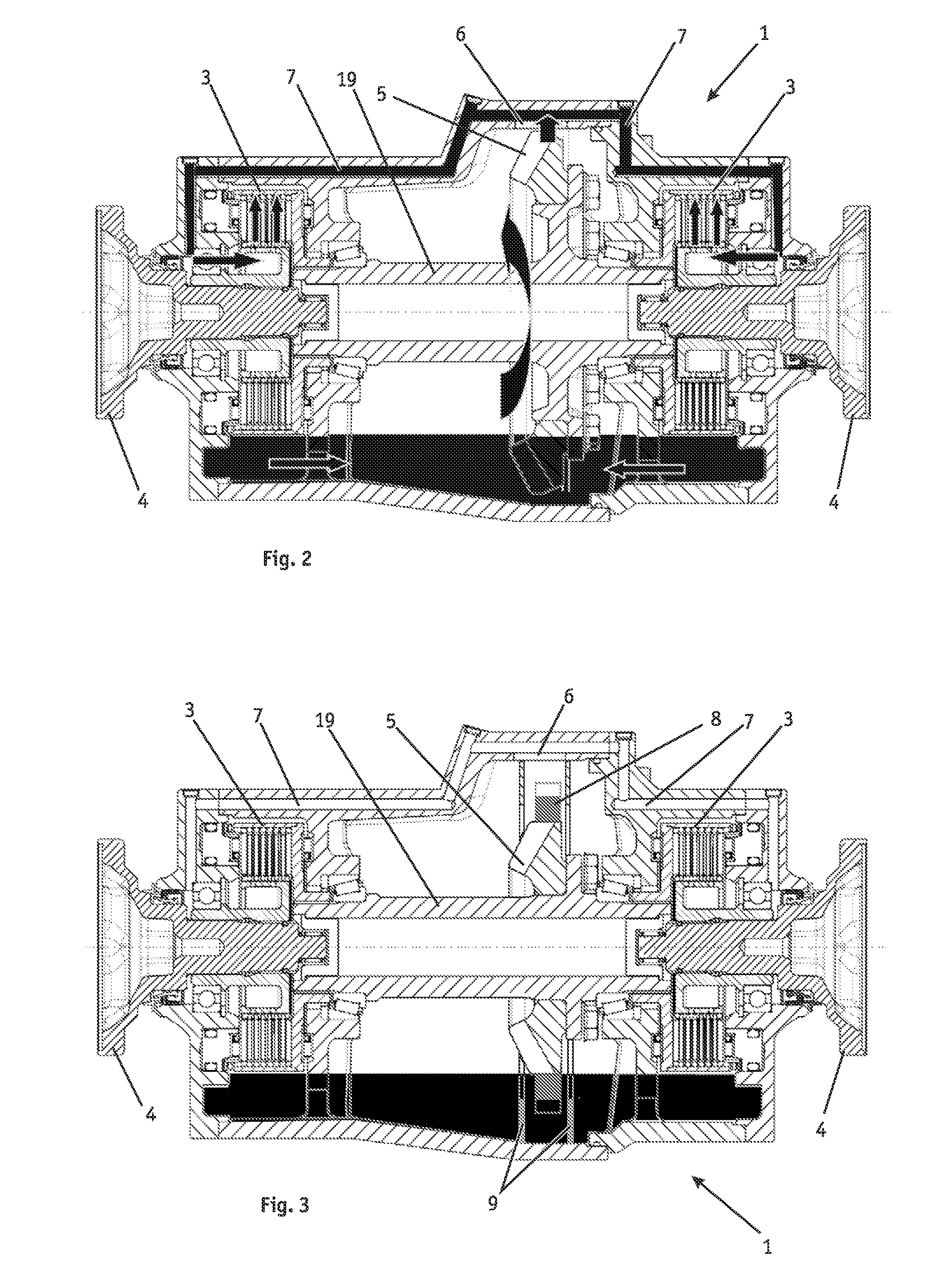
[0009]According to the invention, the object is solved in that the delivery device is formed by a oil delivery wheel arranged distant from the clutch device.

[0010]The arrangement of the oil delivery wheel distant from the clutch device results in that the oil following a passage through the clutch device to be oiled always flows back into the oil sump of the equalizing unit before it is again fed into the oil circuit. Thus, adequate mixing-through of the entire oil volume and consequently th...


PUM


Abstract

The invention relates to an oiling concept of an equalizing unit of a drive train of a motor vehicle with a clutch device to be oiled in driving mode. In order to stop drag torques which act on the clutch device from the outside and result in increased dissipation when said clutch device is not required due to the operating state, measures are provided which promote the dry running of the clutch device. The measures include the spatial-functional separation of the oil delivery device from the clutch device and the provision of a braking or decoupling device by means of which the oil delivery device can be deactivated if there is no oil requirement.

Description

CROSS-REFERENCE TO RELATED PATENT APPLICATIONS[0001]This application is based upon and claims the benefit of priority from prior German Patent Application No. 10 2010 036 826.1, filed Aug. 3, 2010, the entire contents of which are incorporated herein by reference in their entirety.BACKGROUND OF THE INVENTION[0002]The invention relates to an equalizing unit of a drive train of a motor vehicle with a housing and with drive members comprising an input shaft and at least one first output shaft, wherein the first output shaft can be coupled to a second output shaft or to the input shaft or to an intermediate shaft driven by the input shaft via a clutch device, which is to be supplied with oil via a delivery device directly or indirectly driven via the drive members.[0003]The construction of an equalizing unit described above is known from the German disclosure publication DE 10 2008 002 844 A1. There, a drive train for a motor vehicle is shown, which discloses a transverse equalizing uni...

Claims


Application Information

Patent Timeline
IPC IPC(8): F16D13/74
CPCF16H48/19F16H57/0409F16H57/0423F16H57/0424F16H57/0427B60K25/06F16H57/0471F16H57/0473F16H57/0483F16H2048/385B60K17/34F16H57/0457
Inventor NETT, HANS-PETERGOTTERT, CHRISTOPHMULLERS, MICHAELHAUPT, JAN
Owner GKN DRIVELINE KOPING
Why Eureka
Try Eureka