Antenna integrated with a portable communication device

a communication device and portable technology, applied in the direction of resonant antennas, substation equipment, radiating element structural forms, etc., can solve the problems of not being able to design and incorporate a single antenna that operates satisfactorily in all these bands, and not being able to meet the requirements of certain structures

Active Publication Date: 2012-02-02
MOTOROLA SOLUTIONS INC
View PDF3 Cites 29 Cited by
  • Summary
  • Abstract
  • Description
  • Claims
  • Application Information

AI Technical Summary

Problems solved by technology

While the introduction of an additional frequency band provides additional functionality, the design and incorporation of a single antenna that operates satisfactorily in all of these bands may not be feasible for certain structures from a cost or efficiency standpoint or may be unwieldy from the standpoint of user.
However, the use of two or more external antennas may not be desirable, both for reasons above as well as problems such as cost and manufacturing inherent in altering the external structure of an already-existing communication device (e.g., there may be a lack of dedicated volume / space for the additional antenna element).
As above, incorporating an additional external antenna into the physical structure of a pre-existing portable radio is often not feasible due to the manufacturing changes required (e.g., molds, cost).
However, it is often difficult to insert additional components such as an antenna in a structure already dense with physical and electronic objects.
The design and incorporation of an antenna into such a structure is extremely challenging, especially in structures such as the Motorola APX™ 6000 and 7000 in which tolerances are tight.
Moreover, a large amount of metal parts including at least part of the chassis, shielding flex cables and more may be in close proximity (e.g.,
Thus, both the antenna structure and the placement of the antenna within the communication device represent significant challenges.
Thus, as above, design of the antenna is only one part of the solution to the above problems and is inseparable from finding a portion of the communication device relatively free of metal parts and redesigning the surrounding area if necessary.

Method used


Image

  • Antenna integrated with a portable communication device
  • Antenna integrated with a portable communication device
  • Antenna integrated with a portable communication device

Examples


Embodiment Construction

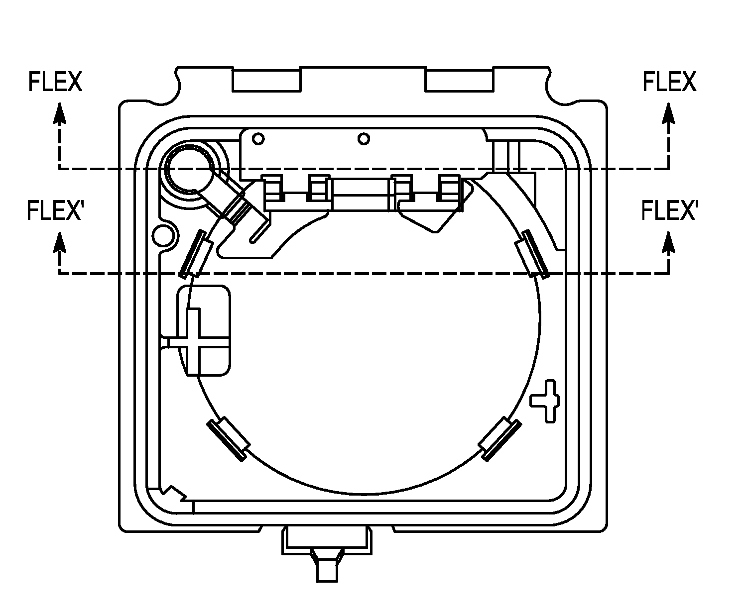
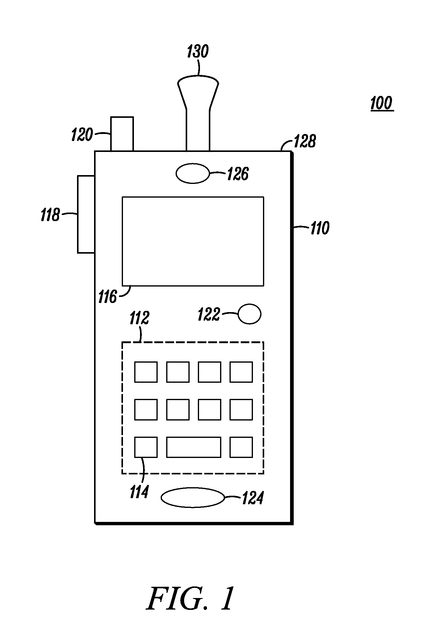
[0015]Before describing in detail the various embodiments, it should be observed that such embodiments reside primarily in combinations of apparatus components related to a radio having antennas designed for short and long range communications. The short-range antenna is a PIFA and is contained internally in the radio chassis in a non-conductive speaker bracket. The speaker bracket also contains a speaker. The PIFA is part of a flexible structure that also contains a contact area, a flexible cable and an extension portion. Feed / ground contact for the PIFA is made in the contact area, as is contact for audio components including a speaker and microphone of the radio. The flexible cable and extension portion of the flexible structure route the audio signals to the audio components. The flexible cable and extension portion are far enough away from the PIFA so that the amount of crosstalk is insignificant. The launch pad where feed / ground contact for the PIFA is made is disposed at a su...


PUM


Abstract

A radio is presented in which a short-range antenna, along with a speaker, is contained within a non-conductive speaker bracket. The antenna is a PIFA that is bent and extends through the speaker bracket so that the distance between the free end of the PIFA and various metallic components of the radio including the chassis and speaker is maximized. The structure containing the PIFA is flexible and also contains a contact area where feed / ground contact for the PIFA is made as well as contact for audio components including a speaker and microphone. A flexible cable and extension portion of the flexible structure routes the signals to the audio components far enough away from the PIFA so that the amount of crosstalk is insignificant. The free end of the PIFA and launch pad where feed / ground contact for the PIFA is made are non-planar.

Description

TECHNICAL FIELD[0001]The present application relates generally to a communication device and in particular to a communication device containing a multi / broadband antenna of reduced size.BACKGROUND[0002]With the ever-increasing demand for portable communication devices, coupled with the advent of disparate technologies, it has been desirable to provide communication devices that operate in different frequency bands. The ability to use multiple frequency bands has many advantages, for example, permitting communications in different locations around the world in which one or more of the different bands are used, providing a backup so that the same information can be provided through the different bands, or permitting different information to be provided to the device using the different frequencies and permitting the device to determine the manner in which to respond to the different information.[0003]While the introduction of an additional frequency band provides additional functional...

Claims


Application Information

Patent Timeline
Patent Type & Authority Applications(United States)
IPC IPC(8): H01Q1/24H01Q1/38
CPCH01Q1/243H01Q9/0421H01Q1/44
Inventor BIT-BABIK, GIORGIAKENS, JODY H.CHAPPELL, THOMAS J.
Owner MOTOROLA SOLUTIONS INC
Why Eureka
Try Eureka