Large Bore Fuel System And Fuel Injector For Same

a fuel injection system and large bore technology, applied in the direction of machines/engines, spray nozzles, mechanical equipment, etc., can solve the problems of fuel leakage along the guide surface becoming unacceptable, the type of fuel leakage problem correspondingly becoming acute, and the difficulty in scaling up proven solutions from smaller bore fuel injection systems to larger bore fuel injection systems, etc., to achieve the effect of reducing the fuel leakage from the fuel injector

Inactive Publication Date: 2012-02-02
CATERPILLAR INC
View PDF0 Cites 1 Cited by
  • Summary
  • Abstract
  • Description
  • Claims
  • Application Information

AI Technical Summary

Benefits of technology

The patent describes a large bore fuel system with a common rail and multiple fuel injectors. Each injector has a cooling inlet and outlet, and a pilot control chamber, intermediate control chamber, needle control chamber, and nozzle chamber. A pilot valve member and control valve member are used to control the flow of fuel. The system also includes a method to reduce fuel leakage between injection events by equalizing pressures in the control valve and needle valve chambers. The technical effects of this patent include improved fuel efficiency and reduced fuel leakage.

Problems solved by technology

As fuel injection pressures continue to rise, this type of fuel leakage problem can correspondingly become more acute.
Thus, in high pressure common rail systems associated with large bore fuel systems, the fuel leakage along guide surfaces can become unacceptable.
Simply scaling up proven solutions from smaller bore fuel injection systems to larger bore fuel injection systems can also be problematic.
First, the physics with regard to fluid dynamics, mass properties and pressures, etc. do not scale well.

Method used


Image

  • Large Bore Fuel System And Fuel Injector For Same
  • Large Bore Fuel System And Fuel Injector For Same
  • Large Bore Fuel System And Fuel Injector For Same

Examples


Embodiment Construction

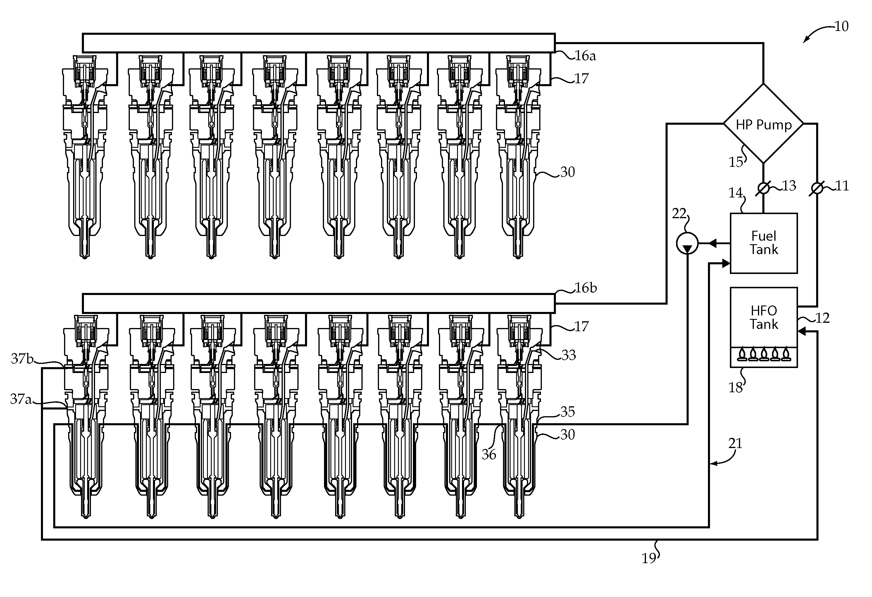
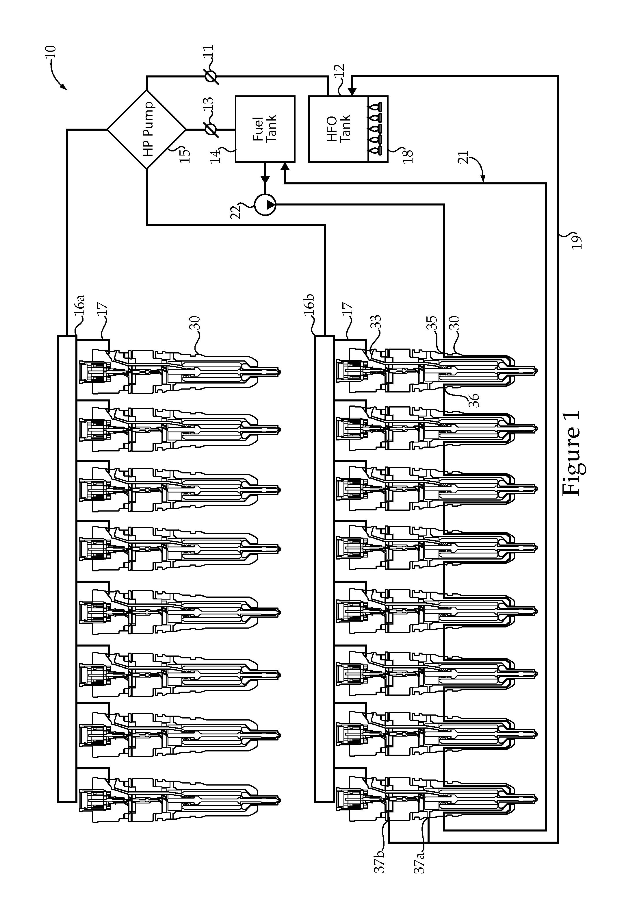
[0011]Referring to FIG. 1, an example of a low leakage large bore fuel system 10 according to the present disclosure is shown. Fuel system 10 is illustrated for a sixteen cylinder large bore engine having a V configuration. Nevertheless, the concepts of the present disclosure are equally applicable to large bore fuel systems for any engine that is configured to inject both heavy fuel oil and distillate diesel fuel. Fuel system 10 includes a source of heavy fuel oil 12 and a source of distillate diesel fuel 14 that are separated from a high pressure pump 15 by valves 11 and 13, respectively. Thus, when valve 11 is open but valve 13 closed, the fuel system 10 injects heavy fuel oil for combustion in the respective combustion spaces of the engine (not shown). For instance, a ship equipped with an engine and fuel system 10 according to the present disclosure might operate in this configuration on the high seas. However, as the ship and fuel system 10 approach a port, valve 11 may be clo...


PUM


Abstract

A low leakage large bore fuel system includes a common rail fluidly connected to at least one of a source of heavy fuel oil and a source of distillate diesel fuel. A plurality of fuel injectors are fluidly connected to the common rail and each include a cooling inlet and a cooling outlet. Each fuel injector also includes an electrical actuator coupled to a direct operated nozzle check valve by a pilot valve member and a control valve member. Fuel leakage is reduced between injection events by equalizing pressures in a pilot control chamber and an intermediate control chamber that are separated by a guide surface of the control valve member. Also, between injection events the pilot valve member blocks a drain outlet from a common rail inlet of the fuel injector.

Description

TECHNICAL FIELD[0001]The present disclosure relates generally to common rail fuel systems for large bore engines, and more particularly to reducing leakage in a large bore fuel system.BACKGROUND[0002]Common rail fuel injectors spend only a small fraction of their operational time actually injecting fuel, and a vast majority of the remaining time standing by in a pressurized state ready for a subsequent injection event. In many cases, a pressurized area within the fuel injector can be separated from a low pressure area by a guide surface of a movable valve member. Because pressure differentials between the pressurized area and the low pressure area can be relatively high, the pressure gradient tends to cause fuel to migrate up through the guide area to the low pressure region, and this migration of fuel can account for a majority of fuel leakage from a fuel injector. As fuel injection pressures continue to rise, this type of fuel leakage problem can correspondingly become more acute....

Claims


Application Information

Patent Timeline
Patent Type & Authority Applications(United States)
IPC IPC(8): F02D1/06B05B1/30
CPCF02M63/0285
Inventor HANSON, CHRISTOPHER D.LEWIS, STEPHENMOHAMMED, QURSHEED HUSSAIN
Owner CATERPILLAR INC
Why Eureka
Try Eureka