
Method and device for classifying background noise contained in an audio signal

a background noise and audio signal technology, applied in the field of audio signal processing, can solve the problems of disruptive noise in an audio signal, high processing cost of the above method, and inability to interact with background noise, and achieve the effect of not very costly in processing resources and simple application

Active Publication Date: 2012-01-26
FRANCE TELECOM SA
View PDF7 Cites 127 Cited by
  • Summary
  • Abstract
  • Description
  • Claims
  • Application Information

AI Technical Summary

Benefits of technology

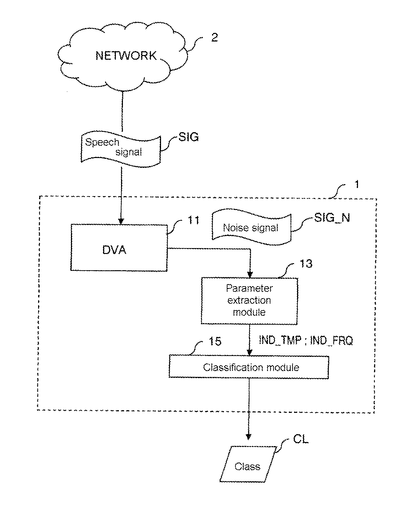
[0015]The object of an exemplary embodiment of the invention is notably to propose a technique for classifying the background noise present in an audio signal, that is relatively simple to apply and that is not very costly in processing resources compared with the known methods, and, in particular, that requires processing resources compatible with the use of this technique in onboard applications, whether it involves, for example, using this technique in applications for measuring voice quality, or applications for processing the speech signal, such as noise reduction or voice recognition.
[0020]By using only two indicators (time and frequency indicators), the method for classifying background noises according to an embodiment of the invention is less costly in terms of computing time than the techniques for classifying audio signals according to the prior art, and therefore can be used in the context of real time applications, for example during real telephone calls. For example, embodiments of the invention may be combined with an onboard real-time noise-removal application in mobile or fixed communication terminals, making it possible to adapt the noise-removal technique used to the nature of the background noise.
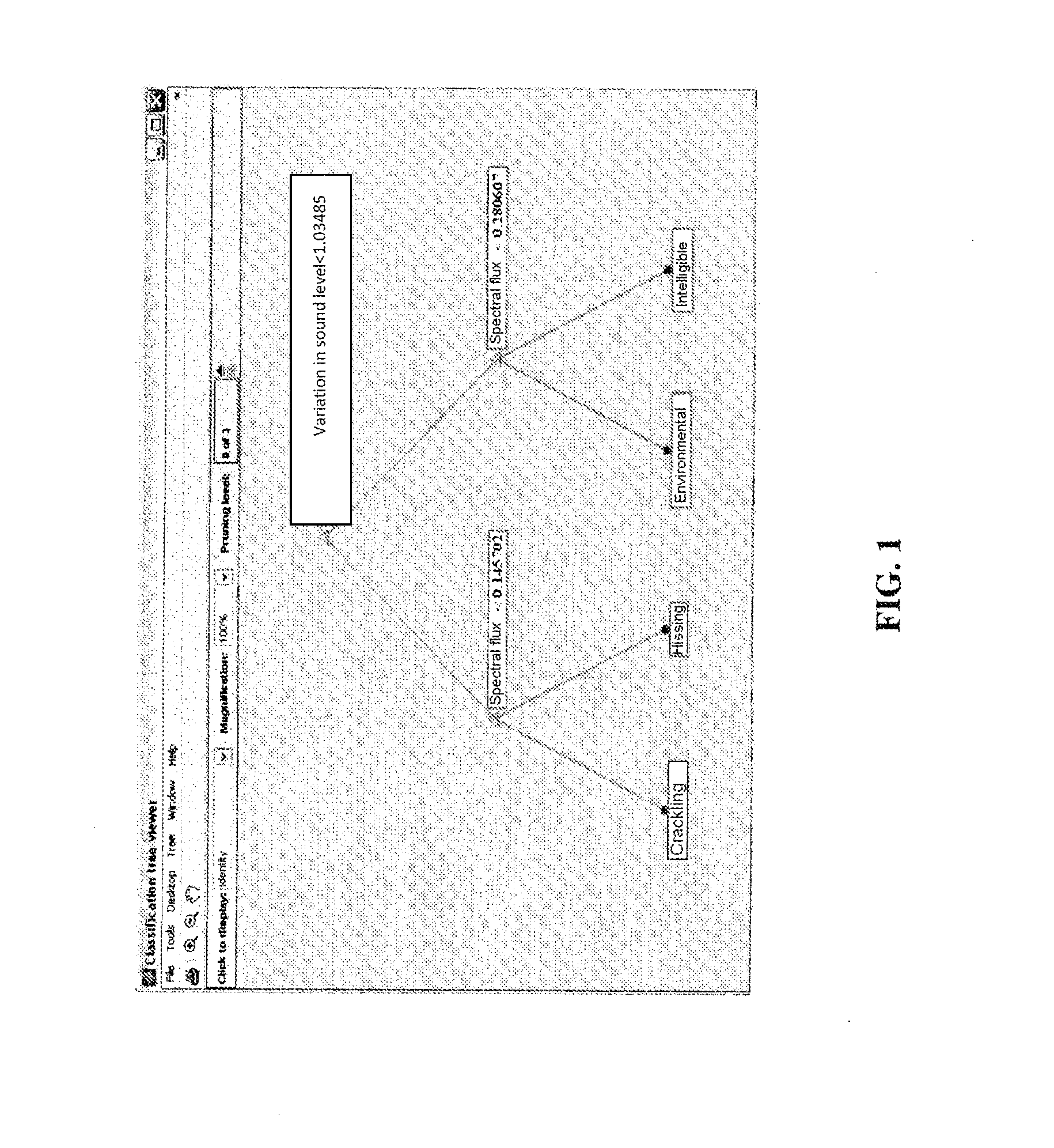
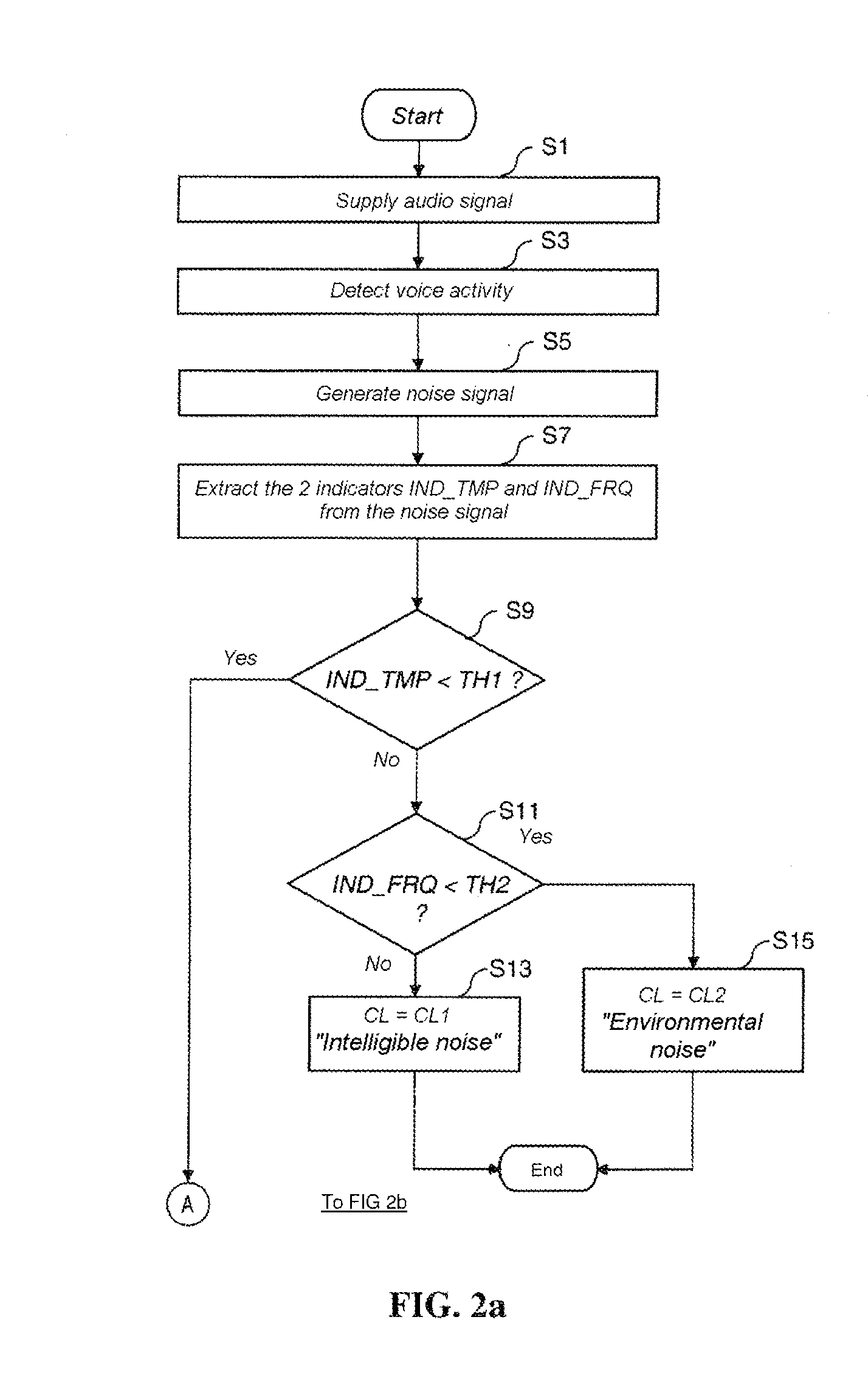
[0021]According to one particular embodiment, the time indicator is obtained from a calculation of variation in the sound level of the noise signal, and the frequency indicator is obtained from a calculation of variation in the amplitude of the frequency spectrum of the noise signal. The combination of these two indicators makes it possible to obtain a low rate of classification errors, while computing them does not place much of a burden on computing resources.
[0031]The use of the aforementioned 3 thresholds TH1, TH2, TH3 in a simple classification tree structure makes it possible to rapidly classify a noise signal sample. Moreover, by calculating the class of a sample over windows of short duration, it is possible to obtain an update in real time of the class of background noise of the noise signal analyzed.

Problems solved by technology

The presence of noise in an audio signal can be disruptive because the noise can mask the specific features of the payload signal (speech or music for example).
Moreover, in addition to the noises coming from the environment in which the sound pick-up takes place, spurious noises, produced notably during the encoding and transmission of the audio signal over the network (packet loss, for example, in voice over IP), may also interact with the background noise.
However, the aforementioned method is extremely costly in terms of processing time given the high number of indicators used.
However, the classified noises are of too precise type, with easily identifiable frequency characteristics and, on the other hand, this technique is also quite costly in terms of processing resources.
However, the latter technique also uses indicators (LSF) that are costly to compute unless placing oneself in the encoded and non-audio domain.
Therefore, the abovementioned noise classification techniques are complex and require considerable computing time notably because of the type and large number of parameters required to carry out the classification.

Method used


Image

  • Method and device for classifying background noise contained in an audio signal
  • Method and device for classifying background noise contained in an audio signal
  • Method and device for classifying background noise contained in an audio signal

Examples


Embodiment Construction

[0042]An embodiment of the invention proposes a method and a device for classifying the background noise contained in an audio signal. This method and this device are based on the application of a background noise classification model constructed in advance and on which the method of construction according to an embodiment of the invention is described below.

[0043]1) Construction of the Model for Classifying Background Noises

[0044]The construction of a model for classifying noise takes place conventionally according to three successive phases. The first phase consists in determining a sound base consisting of audio signals containing various background noises, each audio signal being labeled as belonging to a given class of noise. Then, during a second phase, a certain number of predefined characteristic parameters (here termed “indicators”) forming a set of indicators are extracted from each sound sample of the base. Finally, during the third phase, called the learning phase, the s...


PUM


Abstract

Embodiments of methods and devices for classifying background noise contained in an audio signal are disclosed. In one embodiment, the device includes a module for extracting from the audio signal a background noise signal, termed the noise signal. Also included is a second that calculates a first parameter, termed the temporal indicator. The temporal indicator relates to the temporal evolution of the noise signal. The second module also calculates a second parameter, termed the frequency indicator. The frequency indicator relates to the frequency spectrum of the noise signal. Finally, the device includes a third module that classifies the background noise by selecting, as a function of the calculated values of the temporal indicator and of the frequency indicator, a class of background noise from among a predefined set of classes of background noise.

Description

CROSS-REFERENCE TO RELATED APPLICATIONS[0001]This application is a Section 371 National Stage Application of International Application No. PCT / FR2010 / 050510, filed Mar. 22, 2010 and published as WO 2010 / 112728 A1 on Oct. 7, 2010, not in English.STATEMENT REGARDING FEDERALLY SPONSORED RESEARCH OR DEVELOPMENT[0002]None.THE NAMES OF PARTIES TO A JOINT RESEARCH AGREEMENT[0003]None.FIELD OF THE DISCLOSURE[0004]The present disclosure relates in general to the processing of audio signals and notably audio signals transmitted in telecommunications systems. The disclosure relates in particular to a method and a device for classifying the background noise contained in an audio signal.[0005]The disclosure applies notably to the speech signals transmitted during a telephone call over a communication network, for example a mobile telephony network or a telephony network over a switched network or over a packet network.BACKGROUND OF THE DISCLOSURE[0006]In acoustics and more particularly in the fi...

Claims


Application Information

Patent Timeline
IPC IPC(8): G10L15/20G06F17/00G10L21/0208G10L25/00
CPCG10L21/0208G10L15/20G10L25/00
Inventor LEMAN, ADRIENFAURE, JULIEN
Owner FRANCE TELECOM SA
Learn More