
Flashlight

a flashlight and flashing technology, applied in the field of flashing lights, can solve the problems of increased production costs, high labor costs, and high cost, and achieve the effects of saving further assembly costs, reducing the number of parts used, and simple manner

Active Publication Date: 2012-01-26
ZWEIBRUDER OPTOELECTRONICS BGMH & CO KG
View PDF1 Cites 2 Cited by
  • Summary
  • Abstract
  • Description
  • Claims
  • Application Information

AI Technical Summary

Benefits of technology

[0008]Preferably, a light-emitting diode (LED) is used as light source that, despite putting out considerable light, produces comparatively little heat. In addition, compared to conventional light bulbs, LED's are characterized by their durability.
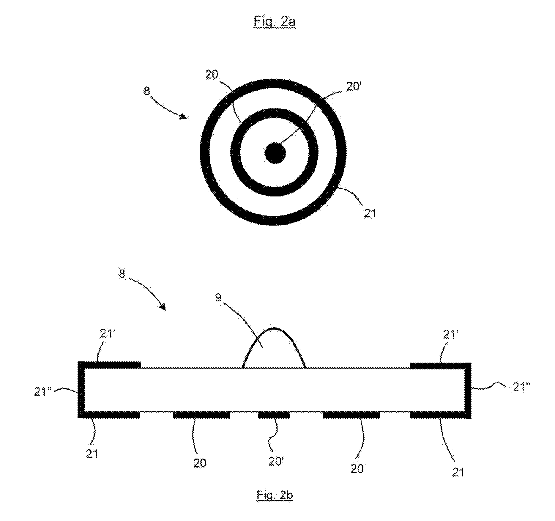
[0012]In order to ensure a secure hold of the support within the flashlight, the lamp-head collar and the casing have respective abutment shoulders for the positive-locking mounting of the support, between which abutment shoulders the support disk is held in the assembled condition. The respective abutment surfaces are configured in a thermally conductive manner so that the heat generated at the LED can be dissipated in an optimal manner.
[0013]Preferably, the lamp-head collar and the casing are connected to each other by a screwthread that is comparatively robust and, at the same time, can be manufactured in a simple manner. In addition, the lamp head and the lamp-head collar are also threaded to each other, for which purpose the lamp head and the lamp-head collar have complementary internal and external screwthreads. A potentially installed reflector lens can be mounted therebetween so that it is captured between the lamp head and the lamp-head collar. Alternatively, the reflector lens can also have a separate threaded section so that it can be screwed into the lamp head, and the lamp head can also be screwed directly onto the casing. This way, the number of parts used is reduced by the part formed by the lamp-head collar, which saves further assembly costs. Of course, it is also possible to fasten the reflector lens in the lamp head by means of a separate support that, for example, can be a cylinder with an adequate external thread. In such a configuration, the lamp head and the lamp-head collar are formed as one piece.

Problems solved by technology

A variety of different shapes and configurations of flashlight is known, often having a plurality of parts that have to be assembled in the factory in a complicated manner and thus with high labor costs.
In addition, there are increased production costs that, due to the high number of different components, are relatively high.
However, a reduction of the parts is often at the expense of a long surface life and durability of the flashlight because certain components have to carry out different functions at the same time within the flashlight.

Method used


Image

  • Flashlight
  • Flashlight
  • Flashlight

Examples


Embodiment Construction

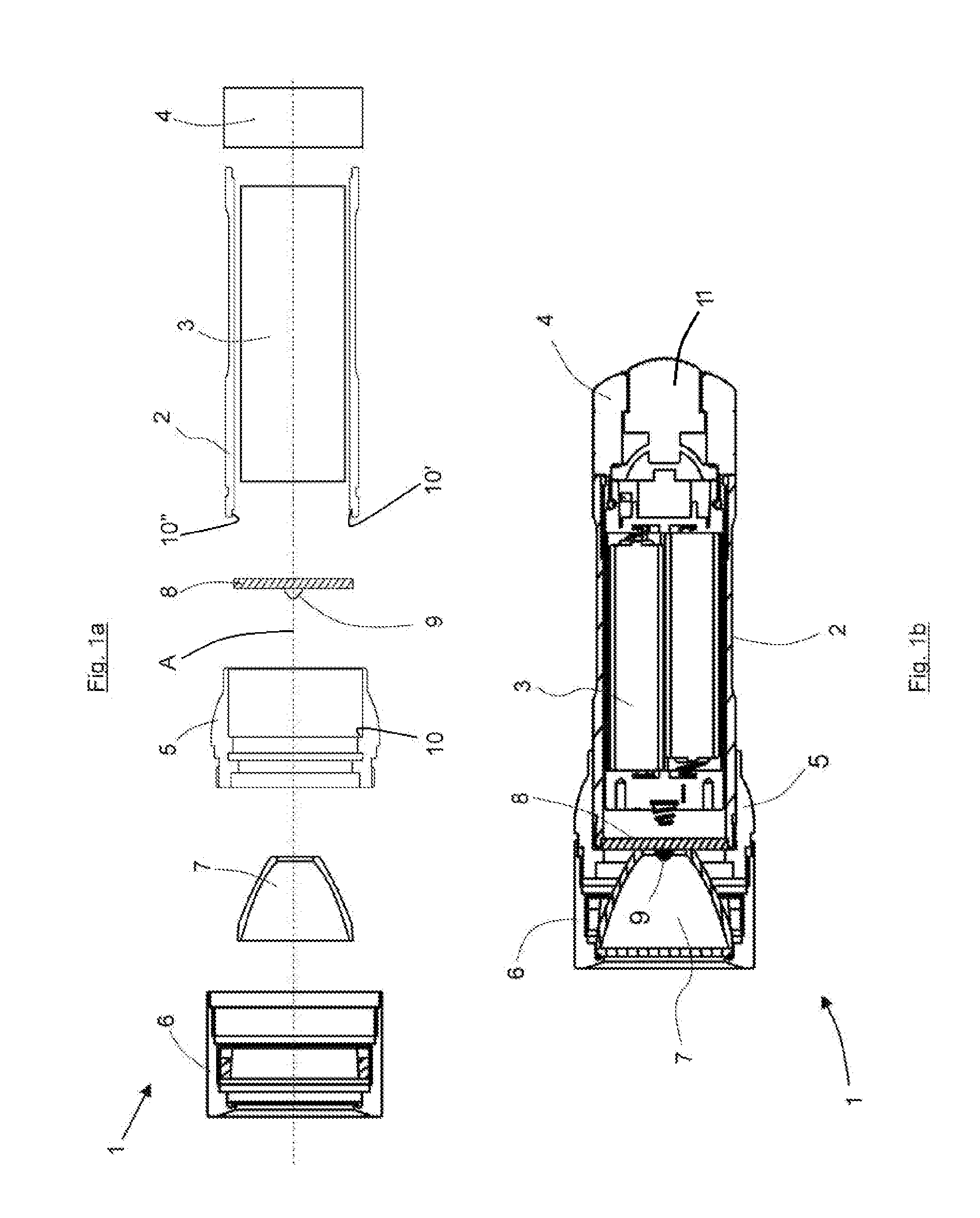
[0019]As seen in FIGS. 1a and 1b a flashlight 1 comprises a cylindrically tubular casing 2 centered on an axis A and holding a battery cartridge 3, an end cap 4, a lamp-head collar 5, a lamp head 6, a reflector lens 7, and a support 8 on which an LED 9 can be mounted.

[0020]In the assembled condition (FIG. 1b), the support 8 is a basically flat circular disk positively held between an axially forwardly directed shoulder 10′ of the casing 2 and an axially rearwardly directed shoulder 10 of the lamp-head collar 5. The front end of the casing 2 has a cylindrical inner surface 10″ terminating rearward at the shoulder 10′ and dimensioned to fit around the cylindrical outer periphery of the disk 8. In the illustrated embodiment the lamp head 6 and lamp-head collar 5 are formed as two pieces, the reflector lens 7 being a separate piece held therebetween.

[0021]In order to ensure an optimal electrical contact between the battery cartridge 3 and the support disk 8, it has as best shown in FIGS...


PUM


Abstract

A flashlight has a casing extending along an axis and having axially opposite front and rear ends, a collar fittable on the front end, a support disk engaged and gripped axially between the collar and the front end, a light source on a front face of the disk, thermally conductive regions on the disk, and a lamp head secured to the collar.

Description

FIELD OF THE INVENTION[0001]The present invention relates to a flashlight.BACKGROUND OF THE INVENTION[0002]A standard flashlight has a normally cylindrical casing, a light source, a lamp-head collar and a lamp head. A variety of different shapes and configurations of flashlight is known, often having a plurality of parts that have to be assembled in the factory in a complicated manner and thus with high labor costs. In addition, there are increased production costs that, due to the high number of different components, are relatively high.[0003]However, a reduction of the parts is often at the expense of a long surface life and durability of the flashlight because certain components have to carry out different functions at the same time within the flashlight.OBJECTS OF THE INVENTION[0004]It is therefore an object of the present invention to provide an improved flashlight.[0005]Another object is the provision of such an improved flashlight that overcomes the above-given disadvantages,...

Claims


Application Information

Patent Timeline
Patent Type & Authority Applications(United States)
IPC IPC(8): F21L4/04F21L4/00F21Y101/00F21V14/00
CPCF21L4/005F21L4/027F21V15/01F21V29/89F21V29/004F21Y2101/02F21V23/00F21Y2115/10F21V29/507
Inventor OPOLKA, RAINER
Owner ZWEIBRUDER OPTOELECTRONICS BGMH & CO KG
Learn More