
Focusable flashlight

a flashlight and focus technology, applied in the field of flashlights, can solve the problems of two hands being required for focusing, the assembly of flashlights is relatively complex, etc., and achieve the effect of increasing the service life of light sources

Active Publication Date: 2012-01-26
ZWEIBRUDER OPTOELECTRONICS BGMH & CO KG
View PDF6 Cites 13 Cited by
  • Summary
  • Abstract
  • Description
  • Claims
  • Application Information

AI Technical Summary

Benefits of technology

[0007]A flashlight has according to the invention a casing extending along an axis and having a front end, a light source axially secured in the housing inward of the front end, and a two-part connecting sleeve forward of the light source and having a rear part secured in the housing and a front part. Interengaging formations couple the parts together for only limited axial movement relative to each other, but lock them rotationally and prevent axial separation beyond a predetermined limit. A lens is mounted in the front part. A head sleeve secured to the front part extends axially rearward over the front end of the casing so that relative axial movement of the front and rear parts axially shifts the lens relative to the source. The result is a particularly compact focusable flashlight that is is easy to manufacture and easy to operate. Due to the low number of components used, assembly costs are also reduced.
[0009]So that the lamp head can be displaced with respect to the casing, one part has at least one slide arm or guide that extends longitudinally axially and engages a slide surface or arm embodied on the other part. Preferably, the slide arm is of in a cylindrical or partly cylindrical shape. In an embodiment with a cylindrical slide arm, the other part is preferably annular and, guides are provided between the annular part and the guide, so that rotary movement of the annular part is prevented. In an embodiment with a plurality of partially cylindrical slide arms, they are preferably spaced equiangularly. The number of slide arms can vary depending on the size of the flashlight, at least three slide arms and three guides are preferred.
[0011]In order to prevent the lamp head from being accidentally displaced with respect to the casing and thus to the light source, one guide element is preferably arranged so that relative movement of the parts can be performed only against a force. In the simplest case the guide element is an O-ring of rubber or another elastic material, which on the one hand surrounds the casing and on the other hand is sized such that so great a friction is produced between the lamp head and the O-ring that the lamp head can be displaced only deliberately. A guide element of this type can be produced economically and is easily replaced in the case of wear. In addition, the guide element serves as a seal so that no dirt in the form of dust can into the lamp head.
[0013]According to a further embodiment of the present is invention the light source is an LED carried on a holder plate. This holder preferably has electric contacts concentrically in a circular or annular layout on its rear face. These contacts are connected to corresponding electrical contacts of the batteries. Furthermore, the holder has on the rear side an annular mating surface formed of a heat-conducting material and is in abutment with the casing. The heat produced in the light source is hereby dissipated to the casing, which in particular increases the service life of the light source. Aluminum, brass or copper are in particular suitable as materials.

Problems solved by technology

For the displaceable support of the image carrier, in addition to the lamp head and the casing, at least three further connecting sleeves are provided, namely an adapter, a guide sleeve and a sliding sleeve, so that assembly of the flashlight is relatively complex.
However, this embodiment has the disadvantage that two hands are always required for focusing, the casing being held with one hand and the lamp head being rotated with the other hand.

Method used


Image

  • Focusable flashlight
  • Focusable flashlight
  • Focusable flashlight

Examples


Embodiment Construction

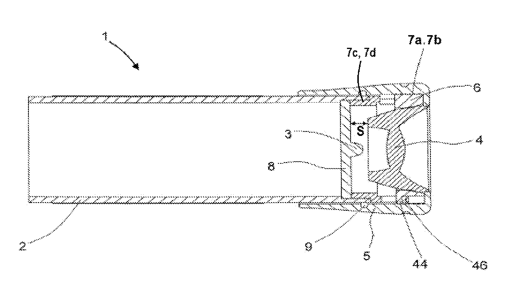
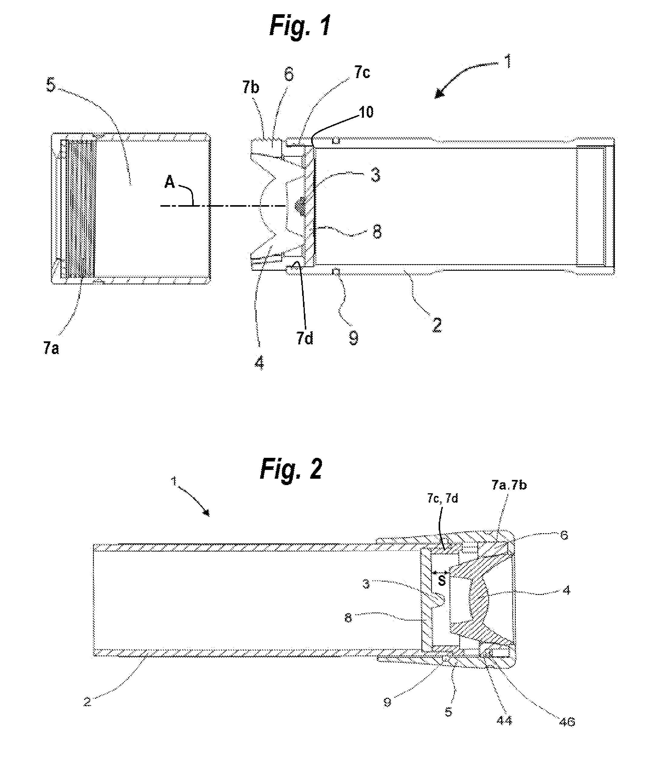
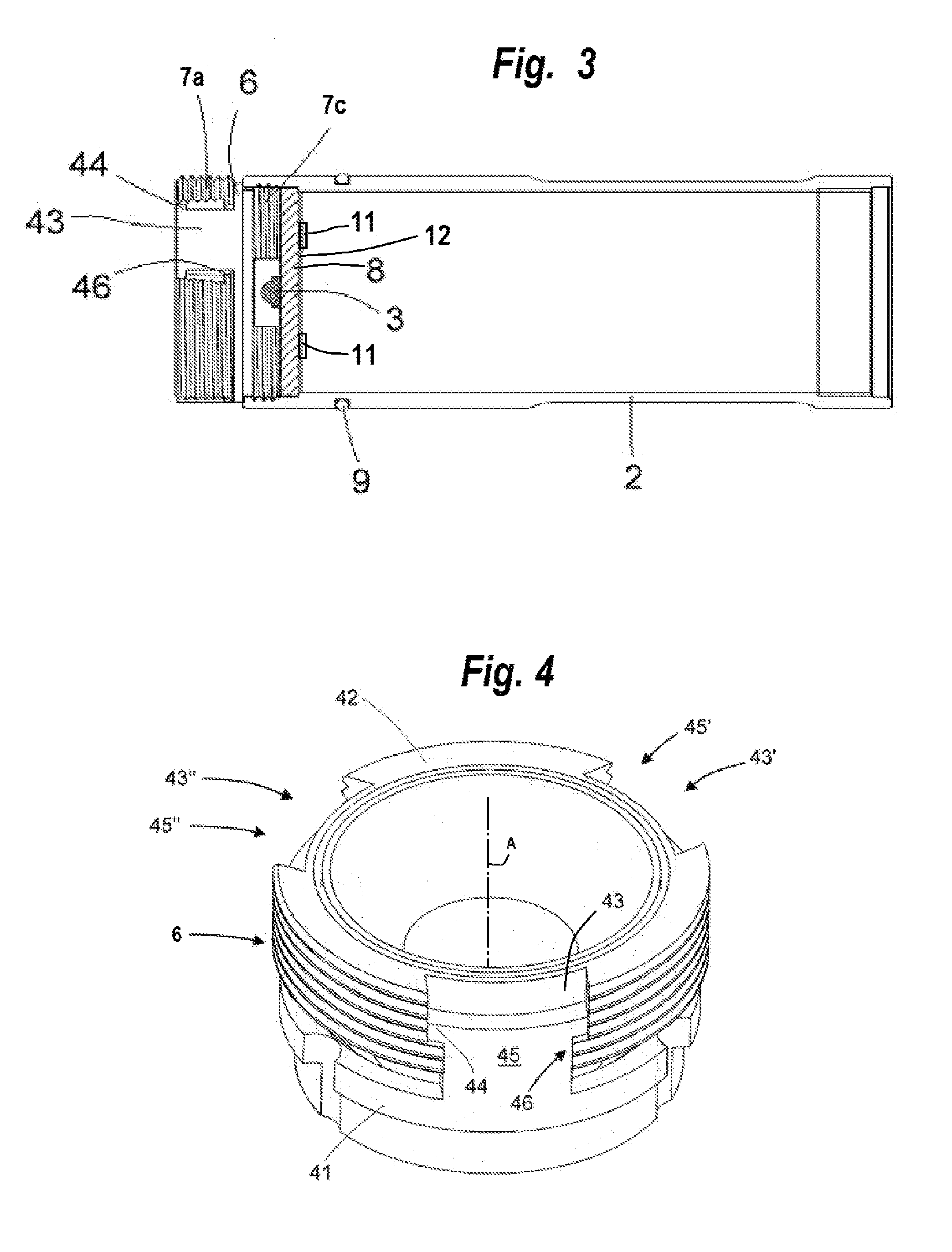
[0019]As seen in FIGS. 1-3 a flashlight 1 according to the invention has a tubularly cylindrical casing 2 centered on an axis A, a light source 3, a lens 4 and a tubular head sleeve 5. A connecting sleeve 6 connected on the one hand to the casing 2 and on the other hand to the lamp head 5. To this end the sleeve 6 has an external screwthread 7a complementary to an internal screwthread 7b of the head 5 and an external screwthread 7c complementary to an internal screwthread 7d of the casing 2.

[0020]The light source 3 is carried on a holder disk 8 that is seated on a forwardly directed shoulder 10 of the casing 2. When assembled, the holder disk 8 is pressed by the connecting sleeve 6 onto the shoulder 10 and thus positively fixed in the casing 2, which forms a battery compartment rearward of this disk 8. Electrical contacts 11 as well as a heat-conducting surface 12 are provided on the back face of the holder 8.

[0021]The front end of the head 5 carries the lens 4 so that it can be lon...


PUM


Abstract

A flashlight has a casing having a front end, a light source axially secured in the housing inward of the front end, and a two-part connecting sleeve forward of the light source and having a rear part secured in the housing and a front part. Interengaging formations couple the parts together for only limited axial movement relative to each other, but lock them rotationally and prevent axial separation beyond a predetermined limit. A lens is mounted in the front part. A head sleeve secured to the front part extends axially rearward over the front end of the casing so that relative axial movement of the front and rear parts axially shifts the lens relative to the source.

Description

FIELD OF THE INVENTION[0001]The present invention relates to a flashlight. More particularly this invention concerns a flashlight whose light beam can be focused.BACKGROUND OF THE INVENTION[0002]A typical flashlight has a casing, a light source and a power source in the casing, and a lens assembly mounted at a head end of the casing. The head-end lens assembly can be shifted longitudinally or axially of the casing relative to the light source to focus light emitted by the source into a controllable beam.[0003]Such a flashlight as disclosed in U.S. Pat. No. 7,040,775 has a casing adapted to hold a battery, a battery-powered LED light source mounted on the casing and directed forward along an axis, and a holder sleeve axially displaceable on the casing forward of and relative to the LED light source. An image carrier, e.g. a slide or a mask, is fixed in the holder sleeve and axially aligned with the light source. An end piece on the casing forward of the LED light source and of the im...

Claims


Application Information

Patent Timeline
IPC IPC(8): F21L4/00
CPCF21V14/065
Inventor OPOLKA, RAINER
Owner ZWEIBRUDER OPTOELECTRONICS BGMH & CO KG
Learn More