
Injectable fluid vial housing

a technology of injectable fluid and vial, which is applied in the direction of identification means, packaging foodstuffs, domestic cooling apparatus, etc., can solve the problems of limiting the practical area available to do, incorrect dosing of an intended recipient, and cumbersome dosing amoun

Active Publication Date: 2012-01-12
SPINLABEL TECH
View PDF11 Cites 31 Cited by
  • Summary
  • Abstract
  • Description
  • Claims
  • Application Information

AI Technical Summary

Benefits of technology

[0015]An objective of the instant invention is to provide a container for a conventional injectable fluid vial housing providing sufficient surface area for inclusion of a dosing calculation aid and providing a means of protecting the fluid vial from tampering.
[0024]Still another objective of the invention is to provide a container that is economical to manufacture and recyclable.

Problems solved by technology

However, the means of calculation the dosing amount is cumbersome and potentially contributing to the incorrect dosing of an intended recipient should any of the base line factors change or an error made in calculation.
Although methods are known by which dose calculating aides may be integrated with typically sized bottles, injectable fluid vials tend to be substantially smaller and thereby greatly limit the practical area available to do so.
The currently available dosage calculations presented on charts and pinwheels are not readily available to the general public.
Even if a physician's reference manual is available, the reference can present a confusing array of dosages that may not be understood by the general consumer.
However, in the midst of the confusion a doctor may not be reached and the first responder may be called upon to determine dosage levels based upon weight, age, fluid volume or area.
It is unrealistic to expect a first responder, or even a seasoned physician, to remember all the required doses for all injectable fluids.
Key does not disclose a container for housing another container, and thus would not disclose any teaching for the matching of two containers.
The skirt has at least a portion thereof extending inwardly in gripping reaction with the neck and limited in removal by contact with the underside of the flange, whereby the cap cannot be removed without destroying a structural integrity thereof.
No known prior art exists for combining an injectable fluid vial with a security container having a calculation aid for dosing.

Method used


Image

  • Injectable fluid vial housing
  • Injectable fluid vial housing
  • Injectable fluid vial housing

Examples


Embodiment Construction

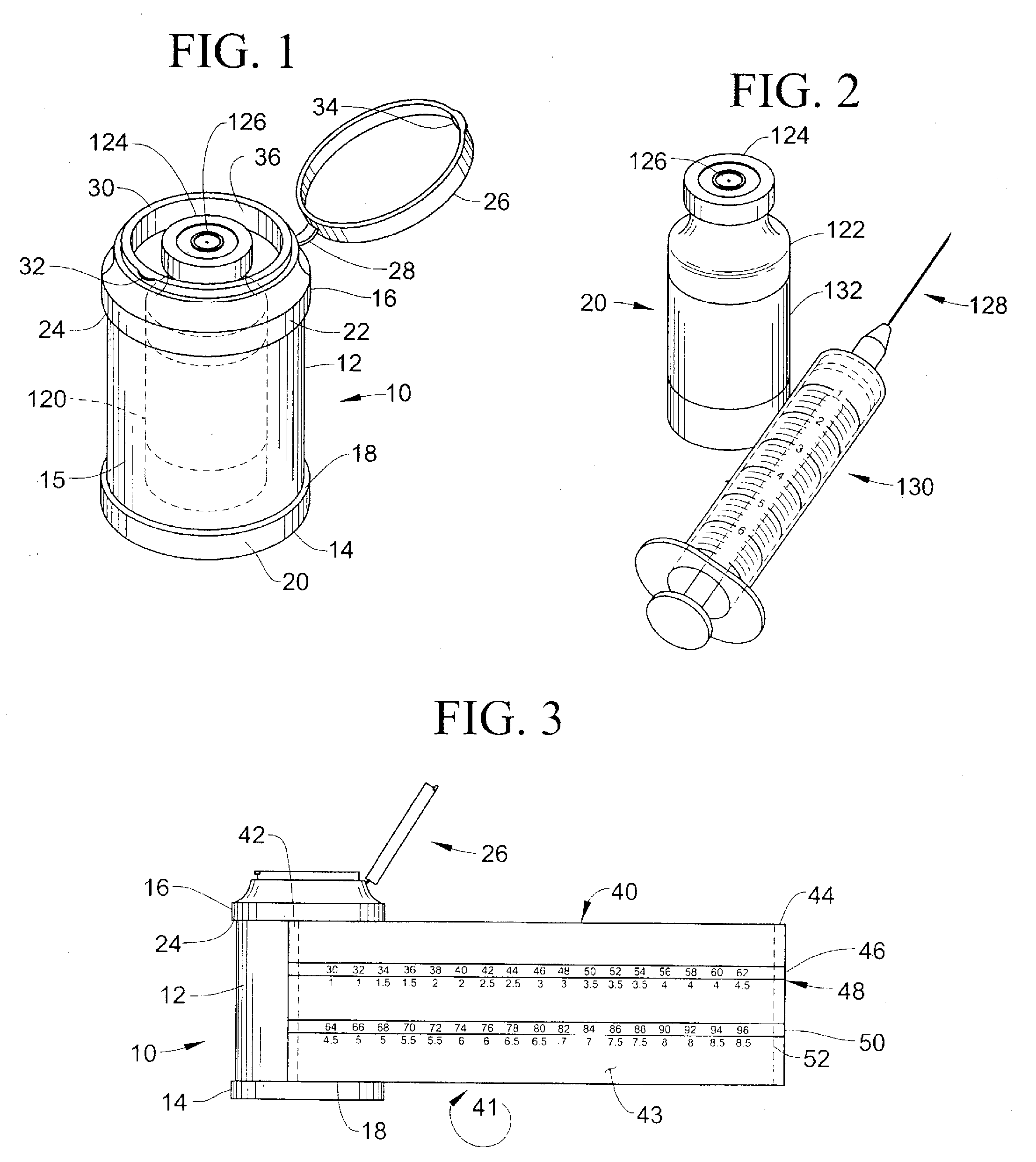
[0037]Now referring to the Figures in general and specifically FIGS. 1 and 2, set forth is a container 10 formed from continuous inset sidewall 12 having bottom section 14 and top section 16. The bottom section 14 may be attached to the inset sidewall 12 or preferably formed integral thereto having a lower transition area 18. The lower transition area 18 is formed by use of an inset sidewall 12 having an outer diameter less than the outer surface sidewall 20 of the bottom section 14; the transition area 18 is preferably formed at a right angle to the inset sidewall 12 and outer surface sidewall 20. Similarly an upper transition area 24 is formed at a right angle to the inset sidewall 12. The inset sidewall 12 has an outer diameter less than the outer surface sidewall 22 of the upper section 16. The use of right angle transition areas 18 and 24 allow the use of a rotating label, as will be further explained in this specification, with sufficient tolerance to allow ease of rotation wi...


PUM


Abstract

A container for housing an injectable fluid vial. The container includes a calculation aid formed specific to the injectable fluid vial. The container is formed from a bottom, a top, and an inset side wall therebetween with a resealable lid. The top includes an opening constructed and arranged to receive the fluid vial housing. Alternatively, the container is formed from two half sections that are hinged together for holding the fluid vial housing therebetween. An inner label is permanently attached to the sidewall having at least one row of dosing indicia coordinated with a base line indicia selected from the group of weight, age, fluid volume or area. An outer label is rotatably secured over said inner label with at least one transparent window allowing selective viewing of the dosing and base line indicia and predetermined dosing rate.

Description

PRIORITY CLAIM[0001]This application claims a priority date of Jul. 8, 2010, based upon U.S. Provisional Patent Application No. 61 / 362,667 entitled “Injectable Fluid Vial Housing,” the contents of which are incorporated herein by reference.FIELD OF THE INVENTION[0002]This invention relates generally to injectable fluid vials potentially containing medicine, vital fluids, and / or nutritional supplements and, more particularly, to a fluid vial container that incorporates a calculation aid to provide dosage level based upon weight, age, volume, or area.BACKGROUND OF THE INVENTION[0003]Dosing of injectable fluids by prescription based upon a patient's weight, age or other means of estimating the patient's fluid volume is known in the art. However, the means of calculation the dosing amount is cumbersome and potentially contributing to the incorrect dosing of an intended recipient should any of the base line factors change or an error made in calculation.[0004]Although methods are known b...

Claims


Application Information

Patent Timeline
IPC IPC(8): B65D85/00B65D50/00B65D81/38
CPCB65D51/002B65D77/0493G09F3/0289G09F2003/0272G09F2003/0248G09F2003/0251G09F3/10
Inventor KAPLAN, BRIANTERWILLIGER, ROBERTHASKINS, RICHARDSCHLIE, PAUL
Owner SPINLABEL TECH
Learn More