
Automatic Waterproof Gate

a gate and automatic technology, applied in the field of gates, can solve the problems of danger and loss to people in the house, the conventional door does not have a waterproof function, etc., and achieve the effects of enhancing the waterproof

Active Publication Date: 2012-01-12
TSENG LI YU
View PDF12 Cites 23 Cited by
  • Summary
  • Abstract
  • Description
  • Claims
  • Application Information

AI Technical Summary

Benefits of technology

[0012]According to the primary advantage of the present invention, when the water level exceeds a preset value, the waterproof door is moved down to press the ground tightly so that the waterproof door blocks the door frame so as to provide a waterproof effect to the door frame.
[0013]According to another advantage of the present invention, the pressing bar is driven downward by the first hydraulic cylinder unit to press the waterproof door downward so that the waterproof door presses the ground tightly so as to enhance the waterproof effect.
[0014]According to a further advantage of the present invention, the waterproof door and the sealing gasket are compressed by the pressing bar so that the waterproof door and the sealing gasket are combined closely so as to enhance the waterproof effect.
[0015]According to a further advantage of the present invention, the push lever is driven downward by the second hydraulic cylinder unit to move the drive lever which is driven to move the pressing plate to abut the waterproof door so as to press the waterproof door transversely toward the waterproof strip and to press the waterproof strip toward the door frame so that the door frame the waterproof strip and the waterproof door are combined closely so as to enhance the waterproof effect.
[0016]Further benefits and advantages of the present invention will become apparent after a careful reading of the detailed description with appropriate reference to the accompanying drawings.BRIEF DESCRIPTION OF THE SEVERAL VIEWS OF THE DRAWING(S)
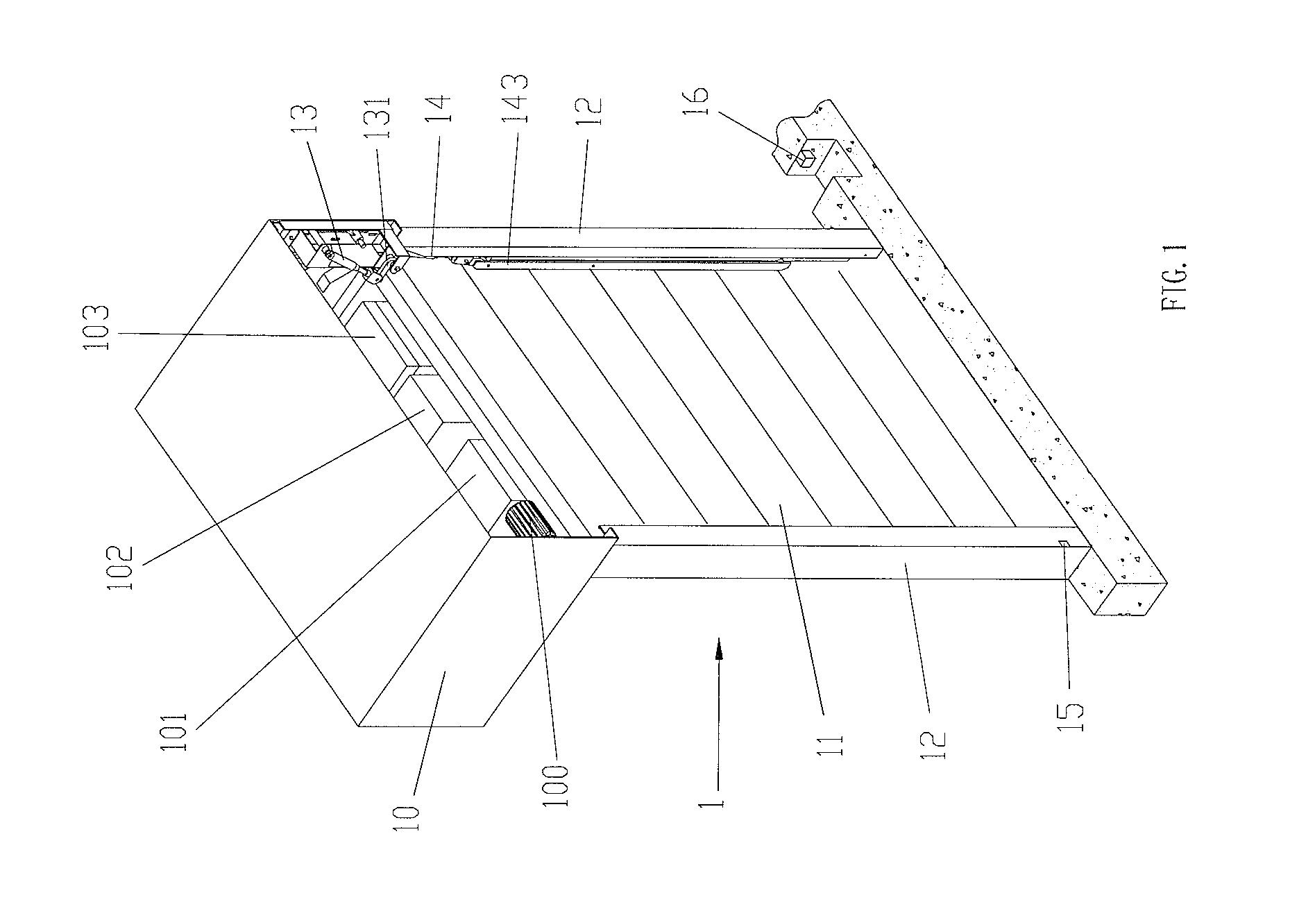
[0017]FIG. 1 is a perspective view of a waterproof gate in accordance with the preferred embodiment of the present invention.

Problems solved by technology

However, the conventional door does not have a waterproof function.
Thus, when a natural accident or disaster, such as typhoon, flood and the like, happens, the water level easily exceeds a preset value so that water of the outside will enter the house from the door, thereby greatly causing danger and loss to the people in the house.

Method used


Image

  • Automatic Waterproof Gate
  • Automatic Waterproof Gate
  • Automatic Waterproof Gate

Examples


Embodiment Construction

[0023]Referring to the drawings and initially to FIGS. 1-4, a waterproof gate 1 in accordance with the preferred embodiment of the present invention comprises a door frame 2, two side rails 12 mounted on two opposite sides of the door frame 2, a waterproof door 11 movably mounted between the two side rails 12, at least one sealing gasket 111 mounted on the waterproof door 11, and at least one waterproof strip 112 mounted between the waterproof door 11 and the door frame 2.

[0024]The waterproof gate 1 further comprises a casing 10 mounted on an upper end of the door frame 2, a pressing bar 131 movable to abut an upper end of the waterproof door 11 so as to press the waterproof door 11 downward, and a first hydraulic cylinder unit 13 pivotally connected with the pressing bar 131 to move the pressing bar 131 relative to the waterproof door 11.

[0025]The pressing bar 131 is pivotally mounted in the casing 10 and has a first end pivotally connected with the casing 10 and a second end that ...


PUM


Abstract

A waterproof gate includes a door frame, two side rails mounted on two opposite sides of the door frame, a waterproof door movably mounted between the two side rails, at least one sealing gasket mounted on the waterproof door, and at least one waterproof strip mounted between the waterproof door and the door frame. Thus, when the water level exceeds a preset value, the waterproof door is moved down to press the ground tightly so that the waterproof door blocks the door frame so as to provide a waterproof effect to the door frame.

Description

BACKGROUND OF THE INVENTION[0001]1. Field of the Invention[0002]The present invention relates to a gate and, more particularly, to an automatic waterproof gate for a door.[0003]2. Description of the Related Art[0004]A conventional door comprises a door frame mounted in the wall of a house, a door panel having a first side pivotally mounted on the door frame by a plurality of hinges and a door knob mounted on a second side of the door panel. However, the conventional door does not have a waterproof function. Thus, when a natural accident or disaster, such as typhoon, flood and the like, happens, the water level easily exceeds a preset value so that water of the outside will enter the house from the door, thereby greatly causing danger and loss to the people in the house.BRIEF SUMMARY OF THE INVENTION[0005]In accordance with the present invention, there is provided a waterproof gate, comprising a door frame, two side rails mounted on two opposite sides of the door frame, a waterproof ...

Claims


Application Information

Patent Timeline
IPC IPC(8): E06B7/20E06B11/04E05F15/00E05F15/20
CPCE06B9/0638E06B9/0676E05F15/72E06B2009/6818E06B2009/007E05Y2900/00E05Y2900/106
Inventor TSENG, LUNG-YUAN
Owner TSENG LI YU
Learn More