Multilayer cellulose ester film having reversed optical dispersion
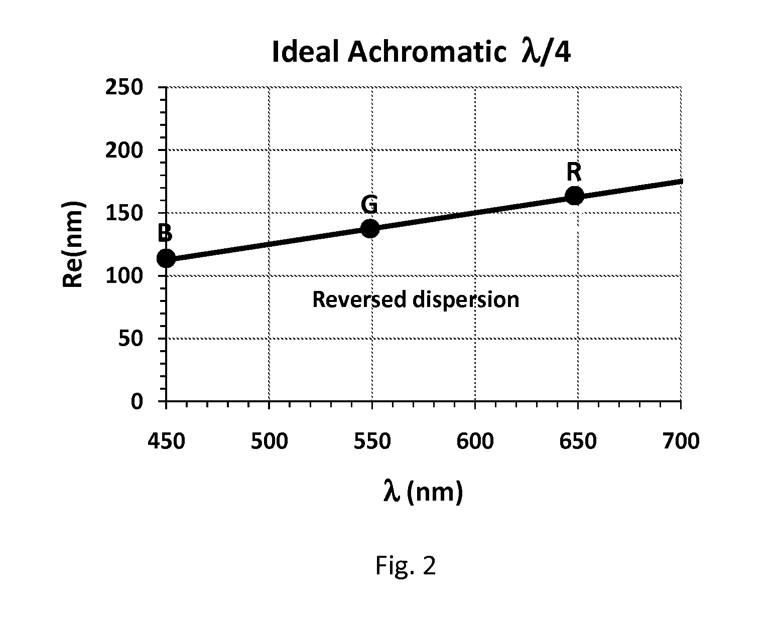
a technology of cellulose ester and optical dispersion, which is applied in the field of multilayer cellulose ester films having reversed optical dispersion, can solve the problems of difficult to achieve, relatively low retardation, and inability to meet certain application requirements, and achieve high optical retardation and reverse dispersion
- Summary
- Abstract
- Description
- Claims
- Application Information
AI Technical Summary
Benefits of technology
Problems solved by technology
Method used
Image
Examples
example 6
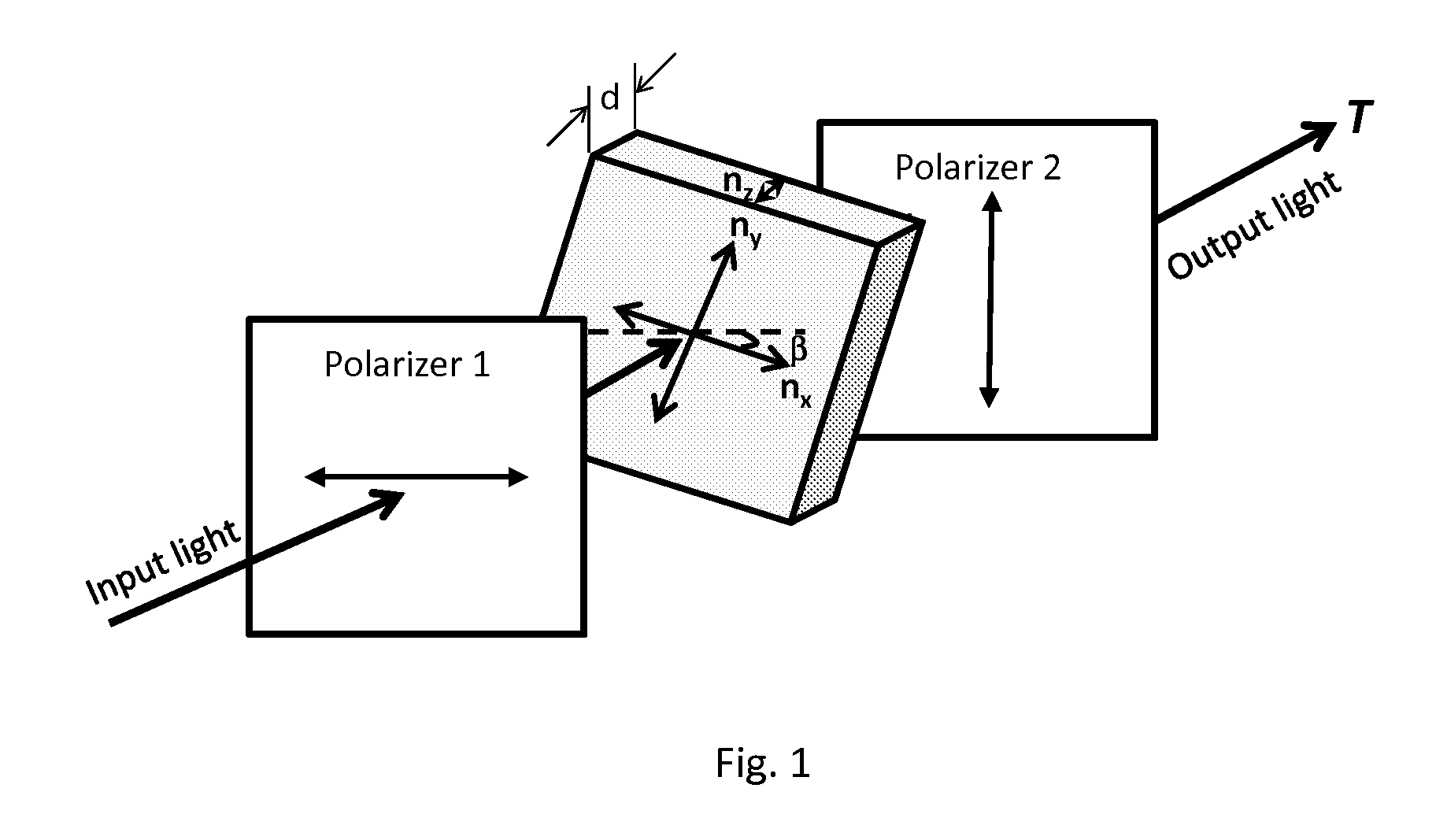
[0094]This example shows the optical retardation and dispersion of a bi-layer optical waveplate prepared by solvent co-casting.
[0095]A randomly (RDS: C6=0.92, C3=1.00, C2=0.96) substituted cellulose acetate propionate (DSAc=1.49, DSPr=1.44, DSOH=0.07) was used to prepare the following solution for layer A for Example 6:
Total solids24gCellulose ester21.6gPlasticizer2.4g Xylitol PentaacetateTotal solvent276gMethylene chloride240.12gMethanol35.88g
[0096]A randomly substituted cellulose acetate propionate (DSAc=0.14, DSPr=1.71, DSOH=1.15) was used to prepare the following solution for layer B for Example 6:
Total solids24gCellulose ester21.6gPlasticizer2.4g Triphenyl phosphateTotal solvent176gMethylene chloride153.12gMethanol22.88g
[0097]Following the general procedure for solution preparation, solutions for layers A and B were independently prepared. The solution for layer B was first cast on a glass plate with a doctor blade at a certain thickness and covered by a pan for 5 minutes. The ...
example 7
[0100]This example shows the optical retardation and dispersion of a tri-layer optical waveplate prepared by solvent co-casting.
[0101]The solutions for layer A and layer B were the same as those in Example 6.
[0102]The solution for layer A was first cast on a glass plate with a doctor blade at a certain thickness and covered by a pan for 4 minutes. The solution for layer B was then cast on top of the layer A and covered by a pan for 4 minutes. Then a third layer using solution A was cast on top of the layer B and covered by a pan for 45 minutes. The cover pan was removed and the tri-layer film was left on the glass plate for an additional 15 minutes. The film was peeled from the glass plate then annealed at 100° C. and 120° C. for 10 minutes, respectively. Films made in this manner were uniaxially or simultaneous biaxially stretched under different stretching conditions. The stretching conditions and optical and film data of these films are listed in Table 7.
TABLE 7Optical properties...
example 8
[0104]This example shows the optical retardation and dispersion of a bi-layer optical waveplate prepared by solvent coating.
[0105]The solutions for layer A and layer B were the same as those of Example 6.
[0106]The solution for layer B was first cast on a glass plate with a doctor blade at a certain thickness and covered by a pan for 45 minutes. The cover pan was removed and the film was left on the glass plate for an additional 15 minutes. The solution for layer A was then coated on top of layer B at a thickness much less than layer B. The coated film was then covered by a pan for 20 minutes. The cover pan was removed and the coated film was left on the glass plate for an additional 20 minutes. The film was peeled from the glass plate then annealed at 100° C. and 120° C. for 10 minutes, respectively. Films made in this manner were uniaxially or simultaneous biaxially stretched under different stretching conditions. The stretching conditions and optical and film data of these films a...
PUM
| Property | Measurement | Unit |
|---|---|---|
| Length | aaaaa | aaaaa |
| Nanoscale particle size | aaaaa | aaaaa |
| Nanoscale particle size | aaaaa | aaaaa |
Abstract
Description
Claims
Application Information
 - R&D
- Intellectual Property
- Life Sciences
- Materials
- Tech Scout
- Unparalleled Data Quality
- Higher Quality Content
- 60% Fewer Hallucinations
Browse by: Latest US Patents, China's latest patents, Technical Efficacy Thesaurus, Application Domain, Technology Topic, Popular Technical Reports.
© 2025 PatSnap. All rights reserved.Legal|Privacy policy|Modern Slavery Act Transparency Statement|Sitemap|About US| Contact US: help@patsnap.com


