Wireless power feeder and wireless power transmission system

Active Publication Date: 2012-01-05
TDK CORPARATION
View PDF0 Cites 16 Cited by
  • Summary
  • Abstract
  • Description
  • Claims
  • Application Information

AI Technical Summary

Benefits of technology

[0014]A wireless power feeder according to the present invention feeds power from a feeding coil to a receiving coil by wireless using a magnetic field resonance phenomenon between the feeding coil and receiving coil. The wireless power feeder includes: a power transmission control circuit; a feeding coil; an exciting coil that is magnetically coupled to the feeding coil and feeds AC power fed from the power transmission control circuit to the feeding coil; a phase detection circuit that detects the phase difference between the voltage phase and current phase of the AC power and generates a phase difference indicating voltage in accordance with the magnitude of the phase difference; and a reset circuit that is connected to a voltage line to which the phase difference indicating voltage is fed so as to reduce the phase difference indicating voltage. The transmission power control circuit includes first and second current paths and makes first and second switches connected in series respectively to the first and second current paths alternately conductive to feed the AC power to the exciting coil. The phase difference indicating voltage output from the phase detection circuit is input to the power transmission control circuit. The power transmission control circuit adjusts the drive frequency so as to reduce the phase difference. The reset circuit reduces the phase difference indicating voltage when the phase difference indicating voltage exceeds a predetermined threshold.
[0015]A wireless power feeder according to a second aspect of the present invention feeds power from a feeding coil to a receiving coil by wireless using a magnetic field resonance phenomenon between the feeding coil and receiving coil. The wireless power feeder includes: a feeding coil; a power transmission control circuit that feeds AC power to the feeding coil at the drive frequency; a phase detection circuit that detects the phase difference between the voltage phase and the current phase of the AC power and generates a phase difference indicating voltage in accordance with the magnitude of the phase difference; and a reset circuit that is connected to a voltage line to which the phase difference indicating voltage is fed so as to reduce the phase difference indicating voltage. The power transmission control circuit includes first and second current paths and makes first and second switches connected in series respectively to the first and second current paths alternately conductive to feed the AC power to the feeding coil. The phase difference indicating voltage output from the phase detection circuit is input to the power transmission control circuit. The power transmission control circuit adjusts the drive frequency so as to reduce the phase difference according to the phase difference indicating voltage. The reset circuit reduces the phase difference indicating voltage when the phase difference indicating voltage exceeds a predetermined threshold.
[0016]When the drive frequency of the power transmission circuit and the resonance frequency are made coincide with each other, the power transmission efficiency in the entire system is enhanced. The current and voltage phases of the AC power are compared to detect the phase difference between them, and the drive frequency is adjusted so as to reduce the detected phase difference, whereby it is possible to allow the drive frequency to track the resonance frequency. As a result, the power transmission efficiency can be kept at a high level.
[0017]The phase difference is indicated by the phase difference indicating voltage. The reset circuit can forcibly reduce the phase difference indicating voltage, so that even if the phase difference indicating voltage is locked to a high value based on an external factor, this locked state can automatically be released. As a result, operation stability of the system is enhanced. The higher the phase difference indicating voltage, the further the power transmission control circuit may increase the drive frequency. In this case, even if a situation where the drive frequency is locked to a significantly higher value than the resonance frequency occurs, this situation can easily be automatically solved by the reset circuit.
[0026]The present invention makes it easy to allow the drive frequency to track the resonance frequency more reliably in wireless power feeding of a magnetic field resonance type.

Problems solved by technology

The type (B) utilizing radio wave is available in a long range; however, it cannot feed big electric power.

Method used


Image

  • Wireless power feeder and wireless power transmission system
  • Wireless power feeder and wireless power transmission system
  • Wireless power feeder and wireless power transmission system

Examples


first embodiment

Half-Bridge Type

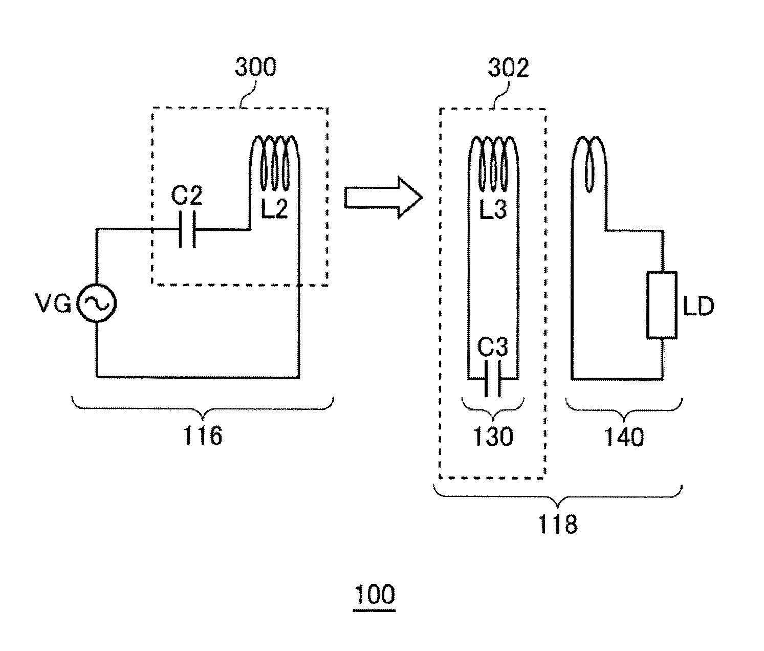
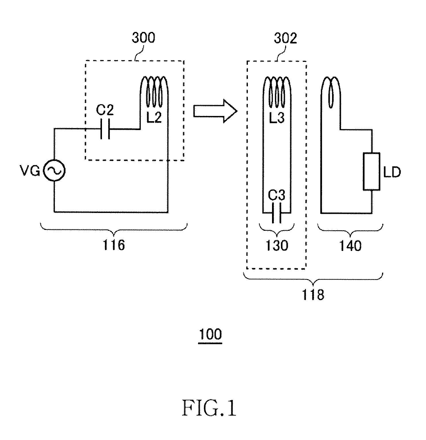
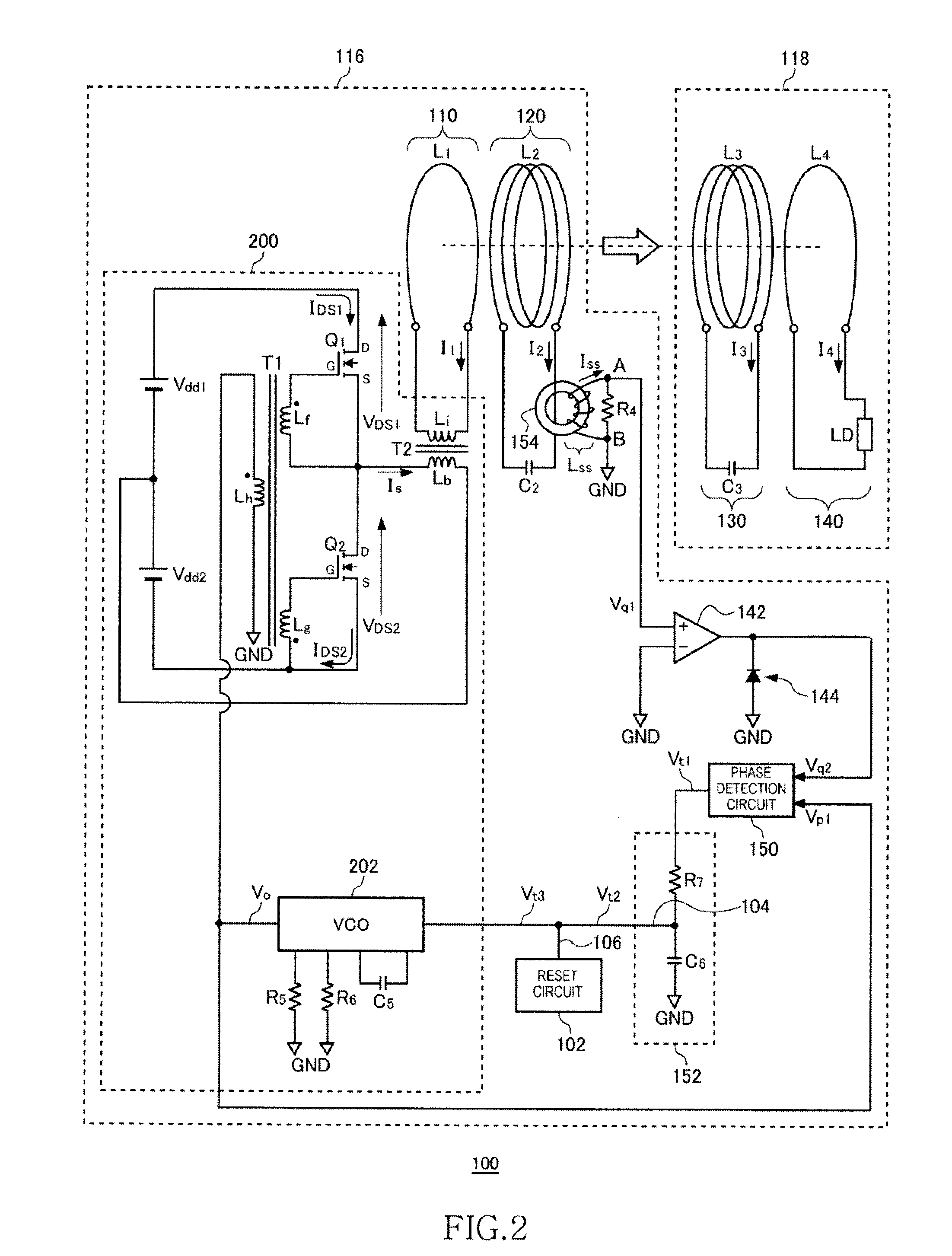
[0048]FIG. 2 is a system configuration view of a wireless power transmission system 100 according to the first embodiment. The wireless power transmission system 100 includes a wireless power feeder 116 and a wireless power receiver 118. The wireless power feeder 116 includes, as basic components, a power transmission control circuit 200, an exciting circuit 110, and a feeding coil circuit 120. The wireless power receiver 118 includes a receiving coil circuit 130, and a loading circuit 140.

[0049]A distance of several meters is provided between a feeding coil L2 of the feeding coil circuit 120 and a receiving coil L3 of the receiving coil circuit 130. The wireless power transmission system 100 mainly aims to feed AC power from the feeding coil L2 to receiving coil L3 by wireless. The wireless power transmission system according to the present embodiment is assumed to operate at a resonance frequency fr1 of 100 kHz or less. In the present embodiment, a resonance freque...

second embodiment

Push-Pull Type

[0108]FIG. 11 is a system configuration view of a wireless power transmission system 108 according to a second embodiment. The wireless power transmission system 108 includes a wireless power feeder 156 and a wireless power receiver 118. The wireless power feeder 156 includes, as basic components, a power transmission control circuit 204, an exciting circuit 110, and a feeding coil circuit 120. A distance of several meters is provided between the feeding coil circuit 120 and receiving coil circuit 130. As in the case of the first embodiment, the wireless power transmission system 108 mainly aims to feed power from the feeding coil circuit 120 to receiving coil circuit 130. Components designated by the same reference numerals as those of FIGS. 2 and 9 have the same or corresponding functions as those described above.

[0109]The exciting circuit 110 is a circuit in which an exciting coil L1 and a transformer T2 secondary coil Li are connected in series. The exciting circui...

third embodiment

Half-Bridge Type

[0128]FIG. 14 is a system configuration view of the wireless power transmission system 100 according to the third embodiment. In the wireless power transmission system 100 of the third embodiment, the capacitor C2 is omitted. Other points are the same as the first embodiment.


PUM


Abstract

Power is transmitted from a feeding coil L2 to a receiving coil L3 by magnetic resonance. A VCO 202 alternately turns ON / OFF switching transistors Q1 and Q2 to feed AC current to the feeding coil L2, whereby the AC power is fed from the feeding coil L2 to the receiving coil L3. An AC magnetic field generated by AC current IS flowing in the feeding coil L2 causes inductive current ISS to flow in a detection coil LSS. A phase detection circuit 150 compares the phase of AC voltage generated by the VCO 202 and phase of the inductive current ISS to detect the phase difference between voltage and current phases and generates phase difference indicating voltage indicating the magnitude of the phase difference. The reset circuit 102 forcibly reduces the phase difference indicating voltage when the phase difference indicating voltage exceeds a predetermined threshold.

Description

BACKGROUND OF THE INVENTION[0001]1. Field of the Invention[0002]The present invention relates to a wireless power feeder for feeding power by wireless and a wireless power transmission system.[0003]2. Description of Related Art[0004]A wireless power feeding technique of feeding power without a power cord is now attracting attention. The current wireless power feeding technique is roughly divided into three: (A) type utilizing electromagnetic induction (for short range); (B) type utilizing radio wave (for long range); and (C) type utilizing resonance phenomenon of magnetic field (for intermediate range).[0005]The type (A) utilizing electromagnetic induction has generally been employed in familiar home appliances such as an electric shaver; however, it can be effective only in a short range of several centimeters. The type (B) utilizing radio wave is available in a long range; however, it cannot feed big electric power. The type (C) utilizing resonance phenomenon is a comparatively ne...

Claims


Application Information

Patent Timeline
IPC IPC(8): H01F38/14
CPCH02J5/005H02J50/50H02J50/12
Inventor URANO, TAKASHI
Owner TDK CORPARATION
Why Eureka
Try Eureka