
Stress-engineered resistance-change memory device

a memory device and resistance-change technology, applied in semiconductor devices, semiconductor/solid-state device details, electrical devices, etc., can solve the problems of not yet developing a commercially viable metal-insulator-metal (mim) stack for resistive random access memory (reram), affecting the performance of a reram element, and not knowing which device operation parameters

Inactive Publication Date: 2012-01-05
INTERMOLECULAR
View PDF1 Cites 12 Cited by
  • Summary
  • Abstract
  • Description
  • Claims
  • Application Information

AI Technical Summary

Benefits of technology

"The present invention relates to a new method for creating resistance-switching memories using stress engineering. The technical effect of this invention is to improve the yield of resistance-cycling devices by using a predictive theory based on experimental data to make a resistance switching device. This method involves using materials with different coefficients of thermal expansion and young's moduluses to create defects in the device that can be used to achieve greater cycling yield. The method also involves pre-forming the current in the device to improve its performance. Overall, this invention provides a new technique for creating reliable and commercially viable resistance-switching memories."

Problems solved by technology

The development of a commercially viable metal-insulator-metal (MIM) stack for Resistive Random Access Memory (ReRAM) has not yet been achieved partly because there is not a detailed, predictive theory for the mechanism determining these devices' cycling properties.
Lacking this, one does not know which device operation parameters have a controlling role in the switching behavior and which ones are dependent variables, or what the relevant material parameters are for the constituent metals and dielectrics in the devices that will make those devices cycle their resistance.
However, other variables may affect the performance of a ReRAM element.

Method used


Image

  • Stress-engineered resistance-change memory device
  • Stress-engineered resistance-change memory device
  • Stress-engineered resistance-change memory device

Examples


Embodiment Construction

[0019]A detailed description of one or more embodiments is provided below along with accompanying figures. The detailed description is provided in connection with such embodiments, but is not limited to any particular example. The scope is limited only by the claims and numerous alternatives, modifications, and equivalents are encompassed. Numerous specific details are set forth in the following description in order to provide a thorough understanding. These details are provided for the purpose of example and the described techniques may be practiced according to the claims without some or all of these specific details. For the purpose of clarity, technical material that is known in the technical fields related to the embodiments has not been described in detail to avoid unnecessarily obscuring the description.

[0020]According to various embodiments, a predictive theory based on experimental data can be used to make a resistance switching device, including what materials should be us...


PUM


Abstract

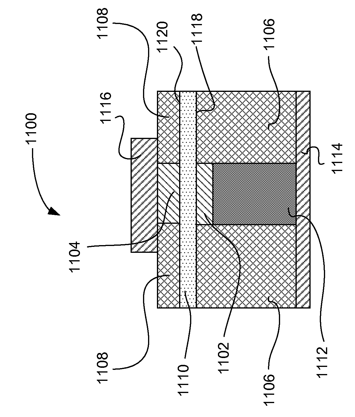
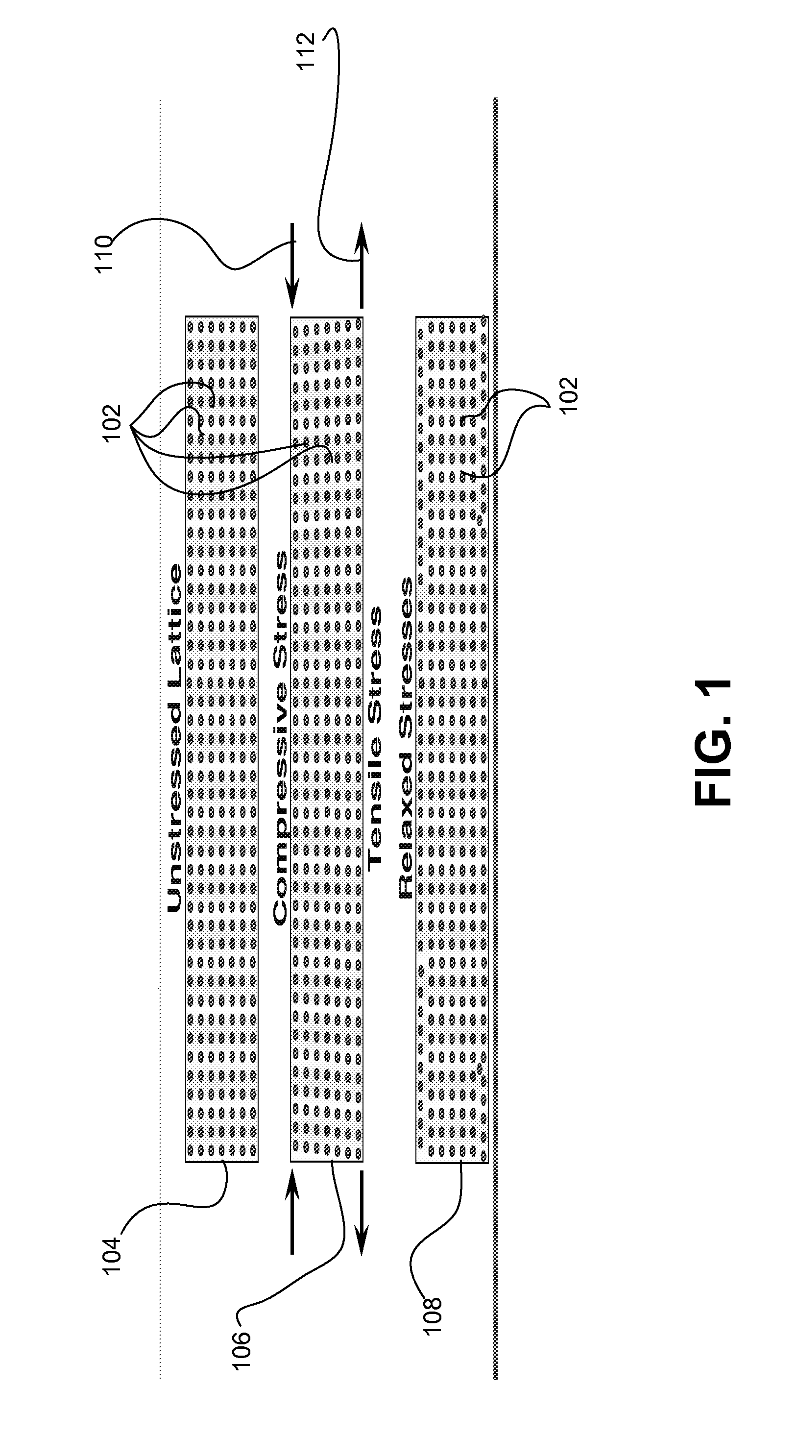
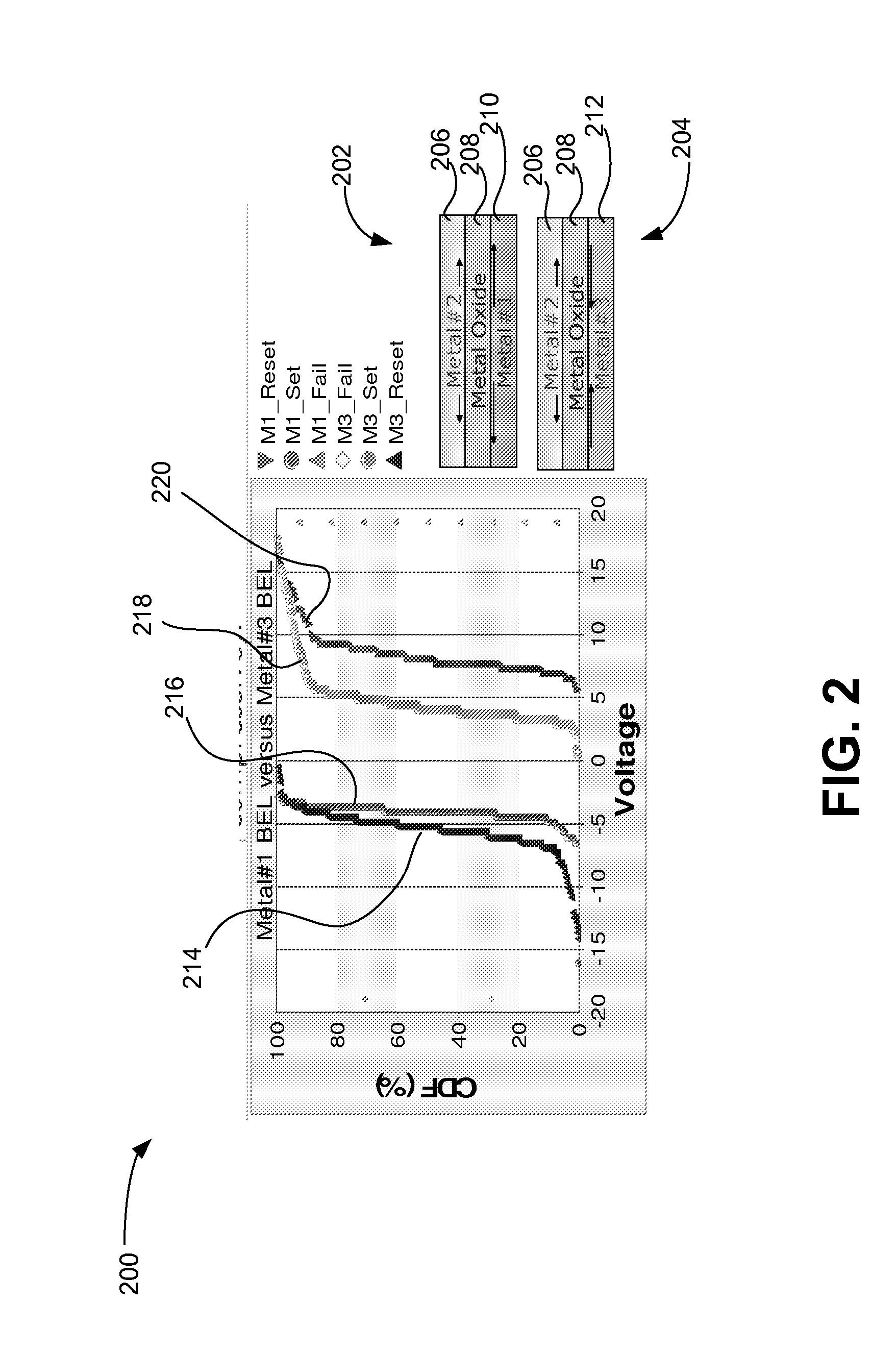
A resistance-change memory device using stress engineering is described, including a first layer including a first conductive electrode, a second layer above the first layer including a resistive-switching element, a third layer above the second layer including a second conductive electrode, where a first stress is created in the switching element at a first interface between the first layer and the second layer upon heating the memory element, and where a second stress is created in the switching element at a second interface between the second layer and the third layer upon the heating. A stress gradient equal to a difference between the first stress and the second stress has an absolute value greater than 50 MPa, and a reset voltage of the memory element has a polarity relative to a common electrical potential that has a sign opposite the stress gradient when applied to the first conductive electrode

Description

PRIORITY CLAIM TO PROVISIONAL APPLICATION[0001]This application is a Continuation of U.S. patent application Ser. No. 12 / 580,196 entitled “Stress-Engineered Resistance-Change Memory Device” filed on Oct. 15, 2009 which is herein incorporated by reference. A claim for priority is hereby made under the provisions of 35 U.S.C. §119 for the present application based upon U.S. Provisional Application No. 61 / 106,141 entitled “Stress-Engineered Resistance-Change Memory Device” and filed on Oct. 16, 2008, which is incorporated herein by reference.CROSS-REFERENCE TO RELATED APPLICATION[0002]This application is related to U.S. Utility application Ser. No. 12 / 255,109 entitled “Non-Volatile Resistive Switching Memories” and filed on Oct. 21, 2008, which is incorporated herein by reference.FIELD OF THE INVENTION[0003]The present invention relates generally to semiconductor memories. More specifically, a stress engineered resistance-change memory device is described.BACKGROUND OF THE INVENTION[00...

Claims


Application Information

Patent Timeline
Patent Type & Authority Applications(United States)
IPC IPC(8): H01L45/00H01L21/02H01L47/00H10N80/00
CPCH01L27/2409H01L45/08H01L45/1233H01L23/5228H01L45/1641H01L23/525H01L45/146H01L2924/0002H10B63/20H10N70/24H10N70/041H10N70/8833H10N70/826H01L2924/00
Inventor MILLER, MICHAELPHATAK, PRASHANTCHIANG, TONY
Owner INTERMOLECULAR
Learn More