
Device for the vibration-reducing transmission of torques

Inactive Publication Date: 2011-12-29
SGF SUDDEUTE GELENKSCHEIBENFAB
View PDF0 Cites 7 Cited by
  • Summary
  • Abstract
  • Description
  • Claims
  • Application Information

AI Technical Summary

Benefits of technology

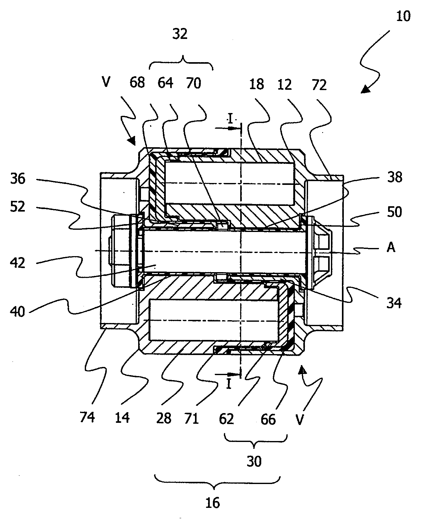
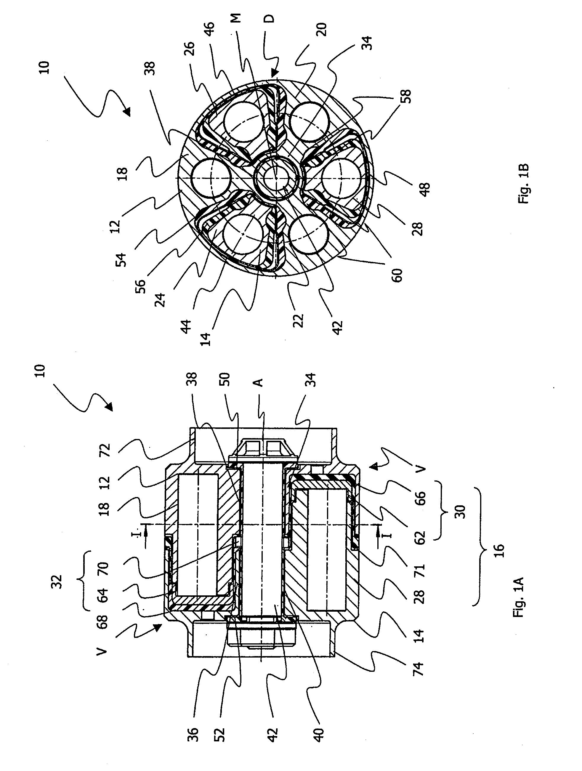
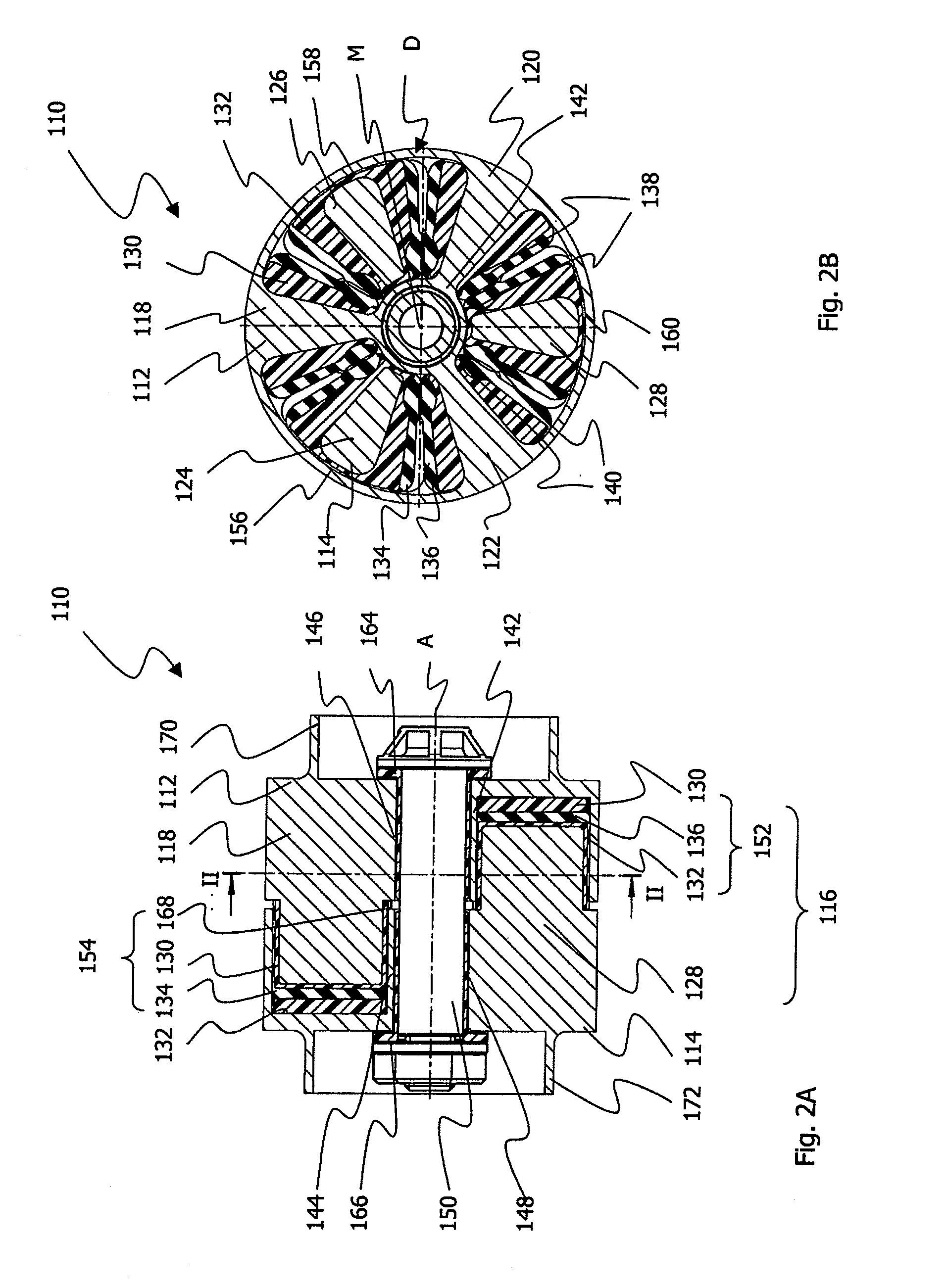
This object is achieved by a device for the vibration-reduced transmission of torques between two shaft sections in a shaft arrangement comprising two transmission parts that interact in a torque-transmitting manner in a coupling area, wherein each of the transmission parts has a protruding claw formation, which is received in a receiving area for the transmission of torque from the respectively other transmission part, wherein a damping device is provided between the transmission parts, wherein each of the transmission parts also has a closed bearing ring with a bearing opening, which receives and supports an axial positioning pin, and wherein the bearing ring is integrally connected to the associated claw formation of the respective transmission part and extends axially into the receiving area. Owing to the use of transmission parts with claw formations protruding in the axial direction, it is possible to transmit even high torques between the shaft sections in a largely loss-free manner, while providing sufficient constructional possibilities for accommodating the vibration-reducing damping device. Furthermore, the transmission parts can each be supported or be mutually guided on a positioning pin, whereby undesired deflections or diffractions of the transmission parts relative to one another can be prevented in the entire rotational speed range and thus also at high centrifugal forces.
For the radial play-free support of the transmission parts on the positioning pin, a preferred embodiment of the invention provides that each of the transmission parts has a closed bearing ring with a bearing opening, which receives and supports the axial positioning pin, wherein the bearing ring is integrally connected to the associated claw formation of the respective transmission part and extends axially into a receiving area of the transmission parts. In this connection, it should further be mentioned that the claws of the claw formation of the one transmission part are received in corresponding receiving openings in the receiving area of the respectively other transmission part. Owing to the closed bearing ring and the simultaneous reception of the claws of the claw formation of the one transmission part in the corresponding receiving openings of the other transmission part, guidance over the entire length of the torque transmission device is achieved, whereby undesired radial deflections or diffractions on account of the centrifugal force at high rotational speeds, e.g. in a drive train, can be avoided. In addition, owing to the bearing rings with the associated bearing openings, the bearings are adapted to the length of the torque transmission device, whereby inexpedient formation of double joints can be avoided.

Problems solved by technology

In particular, such torque transmission devices are required to transmit the torques in as loss-free a manner as possible from one shaft section to the other shaft section, but sufficiently damp vibrations and torsional oscillations which occur, so as not to transmit, for example, structure-borne noise arising at the drive axle through the vehicle.

Method used


Image

  • Device for the vibration-reducing transmission of torques
  • Device for the vibration-reducing transmission of torques
  • Device for the vibration-reducing transmission of torques

Examples


fourth embodiment

A fourth embodiment is described below with reference to FIGS. 4 and 5.

FIG. 4 shows a perspective view of the torque transmission device 310 according to a fourth embodiment of the invention. From FIG. 4 the two transmission parts 312 and 314 and also a section of an intermediate element 376 arranged between these transmission parts 312, 314 can be seen. FIG. 4 further shows the two tubular sections 372 and 374 on the transmission parts 312, 314, by which the transmission parts 312, 314 can be attached to shaft sections (not shown).

FIG. 5 shows a perspective view of the intermediate element 376 with the claw formations 318, 320 and 324, 326 and 328 protruding from a disc-shaped base element 376a.

In addition, it is shown by way of indication in FIG. 5 that the claw formations 318, 320 and 324, 326, 328 are each covered with a rubber coating 354 and 356. In the base element 376a there can be seen between the claws 324 and 328 a through-bore 378 which is provided, for example, in orde...


PUM


Abstract

The present invention relates to a device for the vibration-reducing transmission of torques between two shaft sections in a shaft arrangement comprising two transmission parts that interact in a torque-transmitting manner in a coupling area, wherein each of the transmission parts has a protruding claw formation, which is received in a receiving area for the transmission of torque from the respectively other transmission part, wherein a damping device is provided between the transmission parts, wherein each of the transmission parts also has a closed bearing ring with a bearing opening, which receives and supports an axial positioning pin, and wherein the bearing ring is integrally connected to the associated claw formation of the respective transmission part and extends axially into the receiving area.

Description

TECHNICAL FIELDThe present invention relates to a device for the vibration-reduced transmission of torques between two shaft sections running along a longitudinal axis.BACKGROUNDSuch devices are known from the prior art and are used, for example, to transmit torques in a steering column or in a drive train of a motor vehicle. Precisely in these applications it is necessary to use torque transmission devices which are constructed as compactly as possible on account of the ever-decreasing installation spaces and increasing torque requirements and which couple the shaft sections to one another with damping of torsional oscillations. In particular, such torque transmission devices are required to transmit the torques in as loss-free a manner as possible from one shaft section to the other shaft section, but sufficiently damp vibrations and torsional oscillations which occur, so as not to transmit, for example, structure-borne noise arising at the drive axle through the vehicle. For this...

Claims


Application Information

Patent Timeline
IPC IPC(8): F16D3/70
CPCF16F15/1245F16D3/68
Inventor ROTHE, JOACHIM
Owner SGF SUDDEUTE GELENKSCHEIBENFAB
Learn More