
Sulfur dioxide generator with aqueous gas mixer/aerator

a technology of sulfur dioxide generator and aerator, which is applied in the direction of liquid chemical process, gas-gas reaction process, thin-film liquid gas reaction, etc., can solve the problems of limited device in the maximum burning rate of sulfur per hour, insufficient ability to provide the varying strengths of acids required by farmers for different agricultural applications, and insufficient sulfur burn rate and efficiency. , to achieve the effect of sufficient residence time, sufficient sulfur dioxide, and sufficient sulfur flow resistan

Inactive Publication Date: 2011-12-29
EARTH RENAISSANCE TECH
View PDF1 Cites 2 Cited by
  • Summary
  • Abstract
  • Description
  • Claims
  • Application Information

AI Technical Summary

Benefits of technology

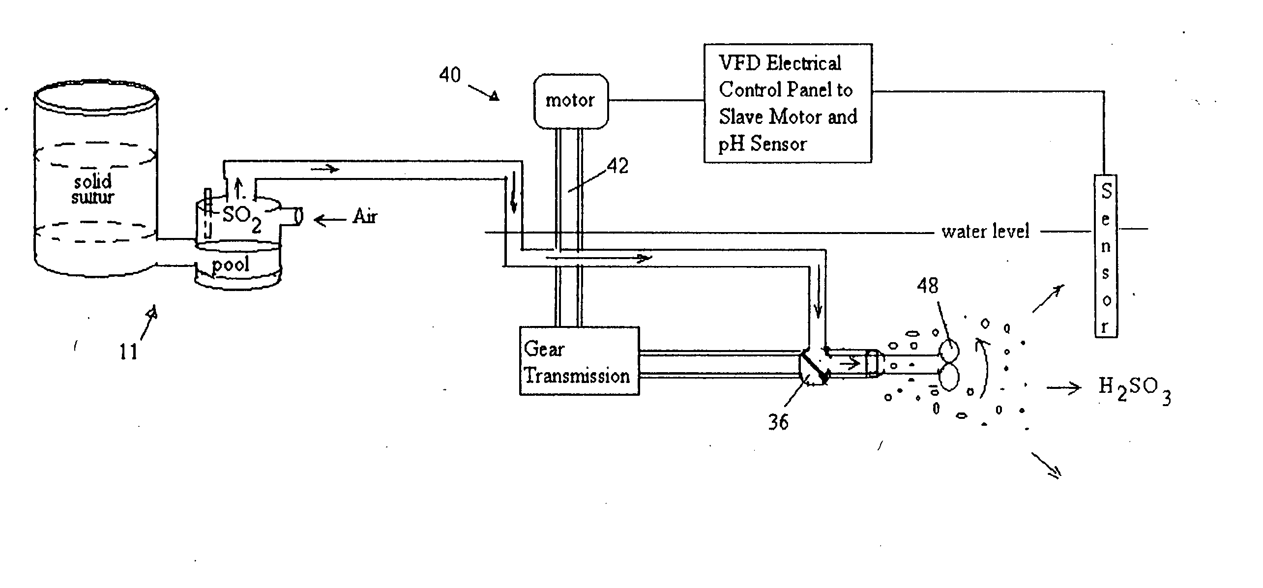
[0012]The sulfur hopper is closely coupled to the sulfur-burn chamber so that the heat of the burning sulfur melts the solid sulfur in the lower segment of the sulfur hopper to insure that molten sulfur is continuously provided to the sulfur pool. This close coupling can be accomplished with a short conduit between the sulfur hopper and the sulfur inlet of the sulfur-burn chamber, where the conduit has a cross-sectional area sufficient to allow enough sulfur to pass into the sulfur-burn chamber from the feed tank at sufficient flow to sustain the maximum burn rate, but sized to provide sufficient sulfur flow resistance to prevent unmelted sulfur from entirely filling the burn chamber.
[0015]Thus, the improved negative air fed sulfurous acid generator and aqueous gas mixer and aerator not only produces a wide range of strengths of sulfurous acid for irrigation, wastewater treatment, and other applications, it also prevents accidental leakage and exposure of the operator to SO2 gas. It further allows the admixing of other gases into waters as part of a comprehensive water treatment cycle.

Problems solved by technology

These devices are limited in the maximum burning rate of sulfur per hour to approximately 7 pounds of sulfur per hour per square foot of burning surface.
The Sulfurous Acid Generator of U.S. Pat. No. 4,526,771 utilizes a positive pressure air feed system which significantly increased the sulfur burn rate and efficiency, but did not provide sufficient ability to provide varying strengths of acids required by farmers for differing agricultural applications.
Also, because of the positive air pressure oxygen feed system, this '771 sulfurous acid generator was subject to sulfur dioxide leaks through breaks in seals, and machine welds which could jeopardize the operator.

Method used


Image

  • Sulfur dioxide generator with aqueous gas mixer/aerator
  • Sulfur dioxide generator with aqueous gas mixer/aerator
  • Sulfur dioxide generator with aqueous gas mixer/aerator

Examples


Embodiment Construction

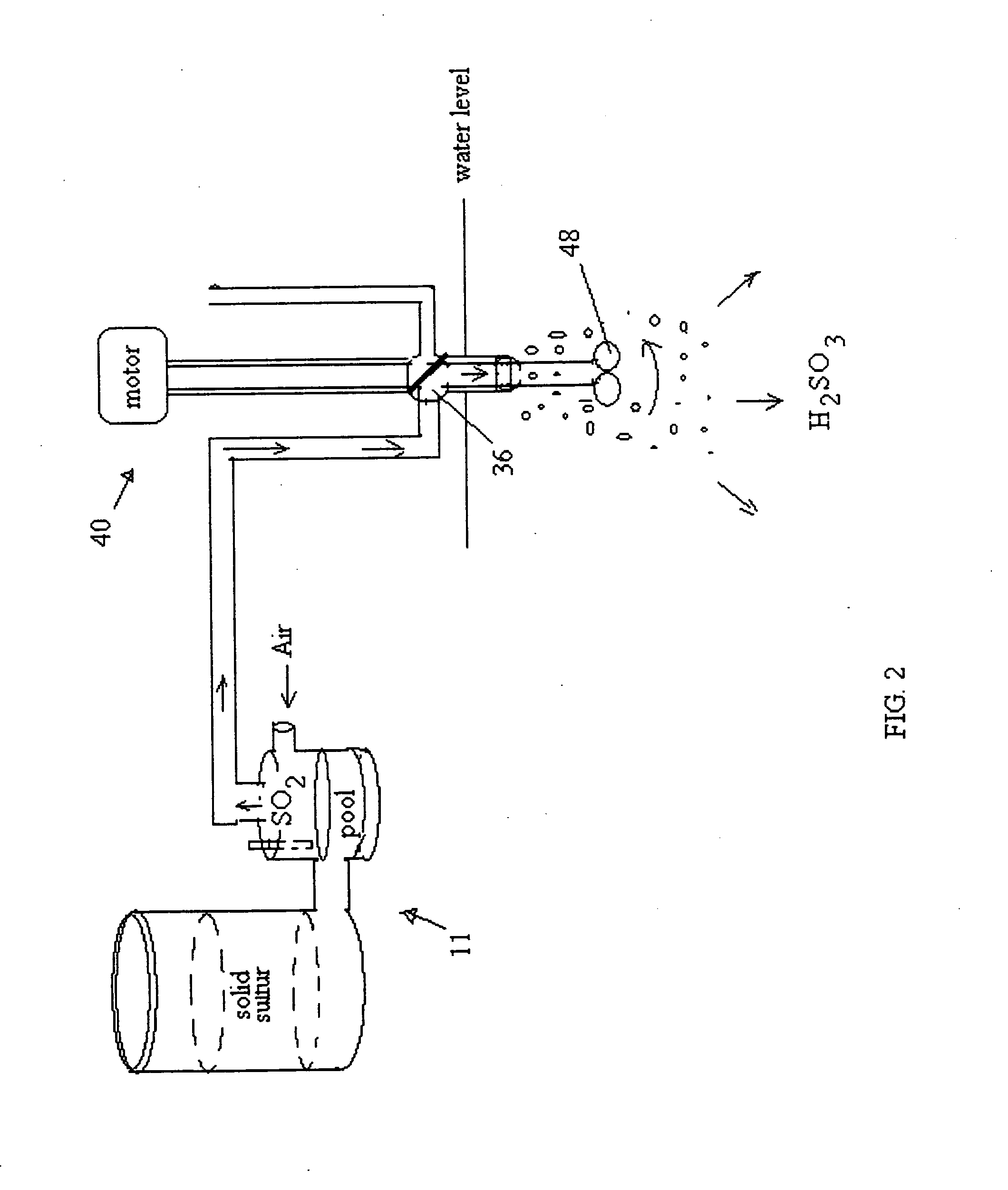
[0024]The present invention comprises a sulfur dioxide generator 11 with aqueous gas mixer and aerator 10 as shown in FIG. 1. It comprises a sulfur Hopper 12 with a removably covered fill port 14 and an outlet 16 structured to hold a supply of solid sulfur and direct it through the sulfur hopper outlet 16. The sulfur hopper outlet 16 is connected to a cyclonic sulfur-burn chamber 18 with a bottom 20 adapted to hold a pool of molten sulfur therein within its bottom 20. To seal the bottom 20, a circular cooling ring and plate 21 shown in FIGS. 4 and 5 is affixed to the bottom as a cleanout to remove periodically any buildup of impurities in the burned sulfur from the sulfur-burn chamber 12.

[0025]The sulfur-burn chamber 18 has a sulfur inlet 22 operably associated with the sulfur hopper outlet 16 at a first lower elevation. A tangential air inlet 24 structured to allow ambient air containing oxygen is in communication with the interior of the sulfur-burn chamber at a second, relatively...


PUM


Abstract

An apparatus for burning sulfur to produce sulfur dioxide, which sulfur dioxide is associated with a multi-channel gas valve associated with other gas sources to selectively be blended each into water by a combination mixer / aerator to aerate water in one monde, admix sulfur dioxide with water to form sulfurous acid in another mode, and stir and mix water without gases in a third mode.

Description

BACKGROUND OF THE INVENTION[0001]1. Field[0002]This invention is directed to an apparatus for burning sulfur to sulfur dioxide, which sulfur dioxide is associated with a multi-channel gas valve associated with multiple gas sources to selectively blended them into water with a combination mixer / aerator to aerate water in one monde, admix sulfur dioxide with water to form sulfurous acid in another mode, and stir and mix water without gases, in another mode.[0003]2. State of the Art[0004]Various sulfur burning sulfur dioxide generators are known and used for various purposes, such as that described in Harmon, U.S. Pat. No. 3,226,201 issued Dec. 28, 1965 entitled “Apparatus for Treating Irrigation Water” burning sulfur to produce sulfur dioxide for injection into irrigation water for pH adjustment. Harmon, U.S. Pat. No. 3,337,989 issued Aug. 29, 1967 entitled “Process of Treating Soil Containing Carbonates” was directed toward burning sulfur to produce sulfur dioxide for injection into ...

Claims


Application Information

Patent Timeline
Patent Type & Authority Applications(United States)
IPC IPC(8): B01J10/00
CPCC02F1/50C01B17/54
Inventor GONG, TERRYHARMON, JOHN
Owner EARTH RENAISSANCE TECH
Learn More