Piezotube borehole seismic source

Active Publication Date: 2011-12-29
RGT UNIV OF CALIFORNIA
View PDF19 Cites 2 Cited by
  • Summary
  • Abstract
  • Description
  • Claims
  • Application Information

AI Technical Summary

Benefits of technology

[0009]In operation, the borehole seismic source apparatus is mounted to a section of borehole tubing. In one embodiment, a segment of borehole tubing is first passed through the defined cylindrical space of the mandrel, and the borehole source thereafter removably secured to the tubing. The securing function can be performed using any suitable means, such as pipe clamps tightened around tabs which extend from the source apparatus. By this arrangement, with the seismic source in place, it is possible to continue normal operation of the well, passing fluid or gas either up or down in direction without interruption. In this manner, the borehole source may be positioned for intermittent use, and left in place for long periods of time, such as days, weeks, months, or even years. This is in stark contrast to sources which are lowered on special lines, and that do not work in the very limited space between production tubing (typically having an outer diameter of about 2.375 inches), and the wall of the borehole (typically as small as about 5 inches), or the inner wall of borehole casing used to clad the hole (typically as small as 4.825 inches for a 5 inch well).
[0012]In another embodiment, a copper braid is either soldered or brazed to each piezoelectric cylinder on the outer radius. The braids can be covered with a protective tape. The braid, or wire conductor, is then fed to a feed through that passes through the top of the piezo housing. Similarly, the inner conductor wire is in electrical contact with the inner radius of the piezoelectric sources, covered if desired with a protective tape, and fed through the piezo housing in an insulated feed-through. Both conductors are passed to the top of the well via cabling that provides for electrical and mechanical isolation of the conductive lines from the harsh environment of the working well.
[0019]The method above may further comprise immersing the individual piezoelectric elements in a dielectric fluid. The fluid prevents breakdown due to high voltages applied to the piezoelectric elements, which result in high voltage field gradients that tend to initiate electrical breakdown and consequent arcing. The applying of a voltage step may comprise applying a sine or square wave AC current with a frequency of 100 Hz to 5 kHz; and applying the sine or square wave current at voltages ranging from ±100 V to 5 kV. In a field experiment, a 1 millisecond wide pulse was applied at a rate of about 10 Hz with voltage amplitudes ranging from 1 kV to 3 kV, although the design of the source would allow higher or lower amplitudes.

Problems solved by technology

Due to the large diameters of the existing sources, concurrent well operation is impractical.
This can be particularly expensive and time consuming when it is desired to take seismic readings at depths of several thousands of feet over extended periods of time.
As can be readily seen, such procedure is fraught with the possibility of borehole damage, and is extremely time consuming and labor intensive.

Method used


Image

  • Piezotube borehole seismic source
  • Piezotube borehole seismic source
  • Piezotube borehole seismic source

Examples


Embodiment Construction

Definitions

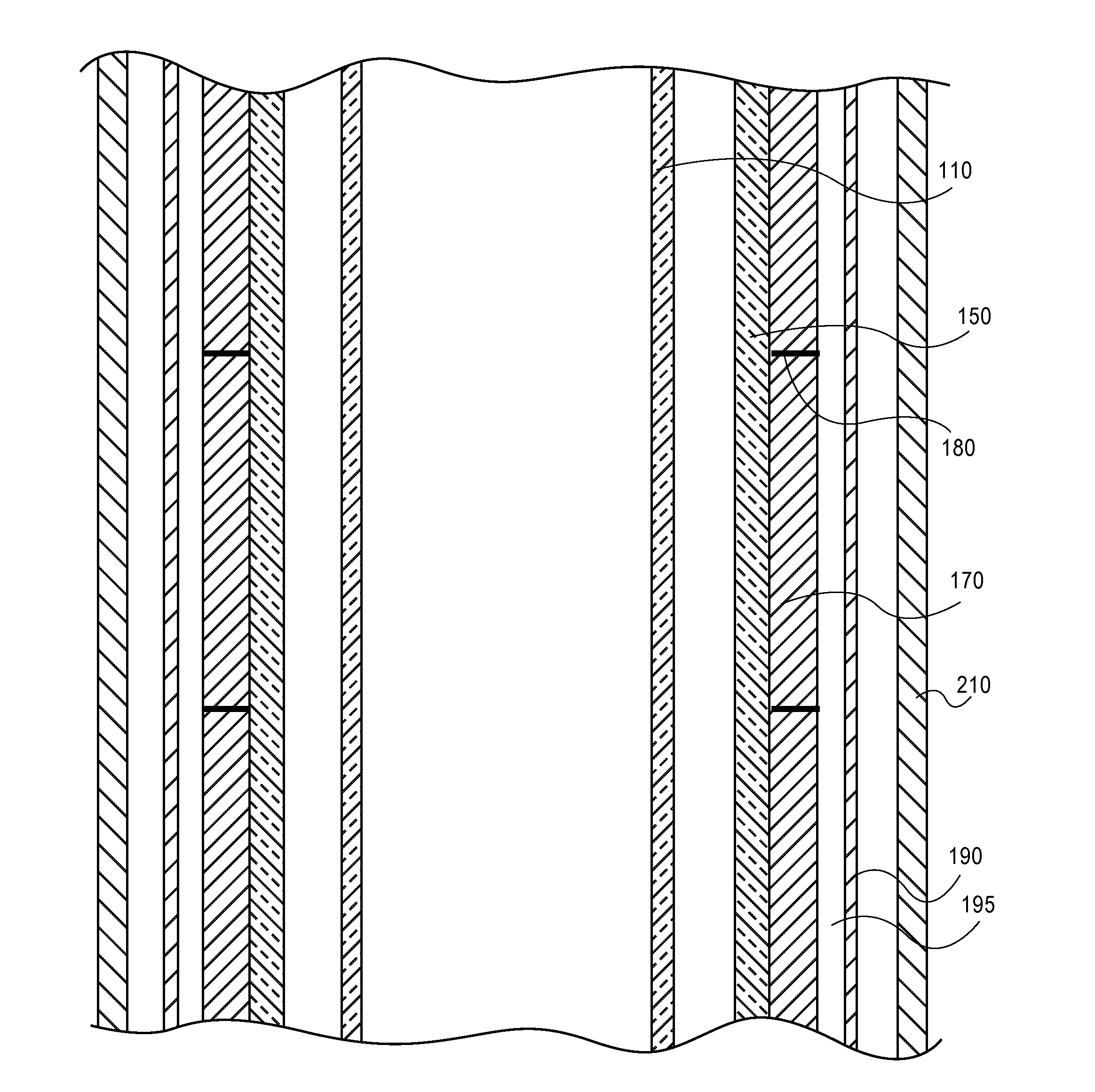
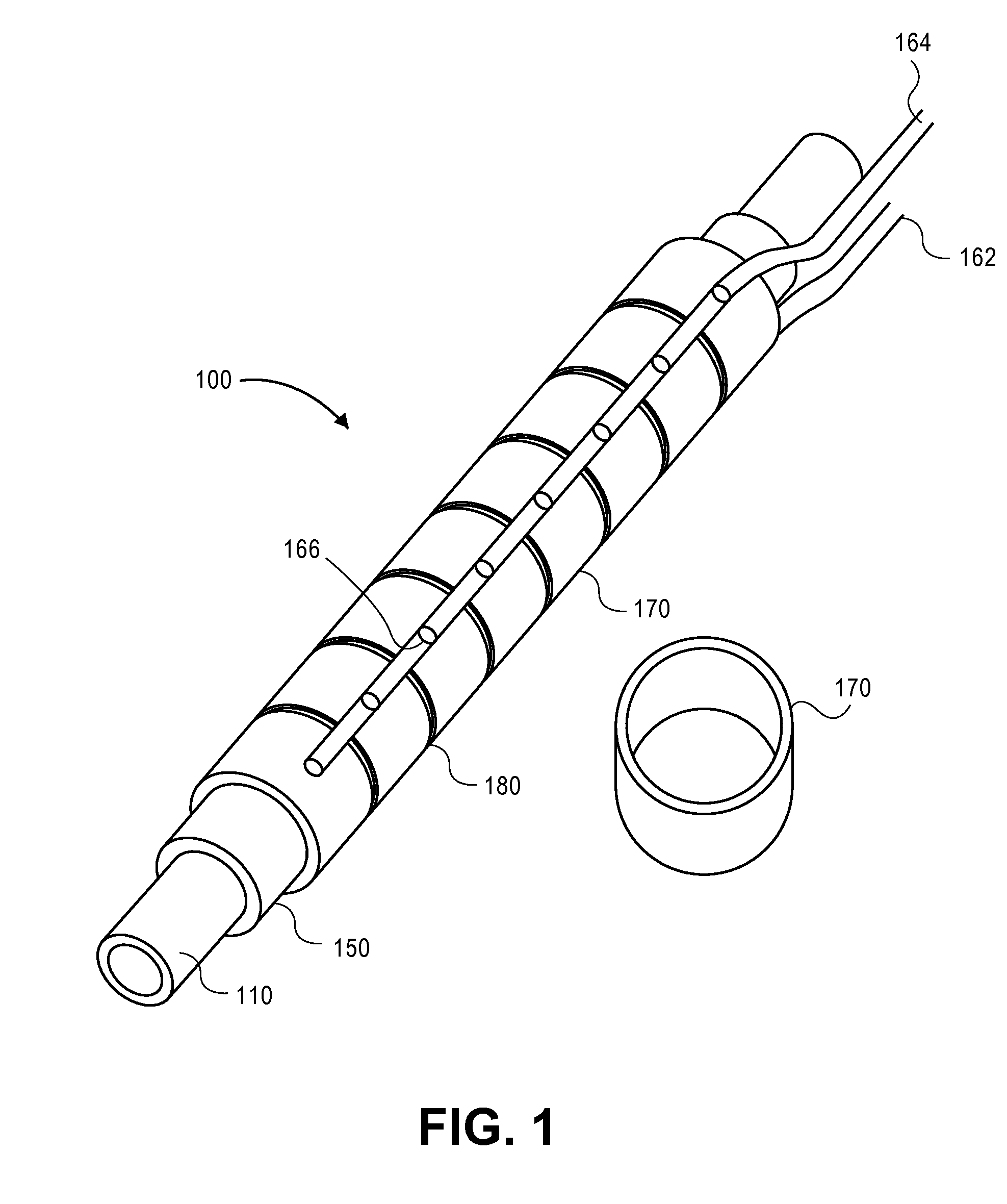
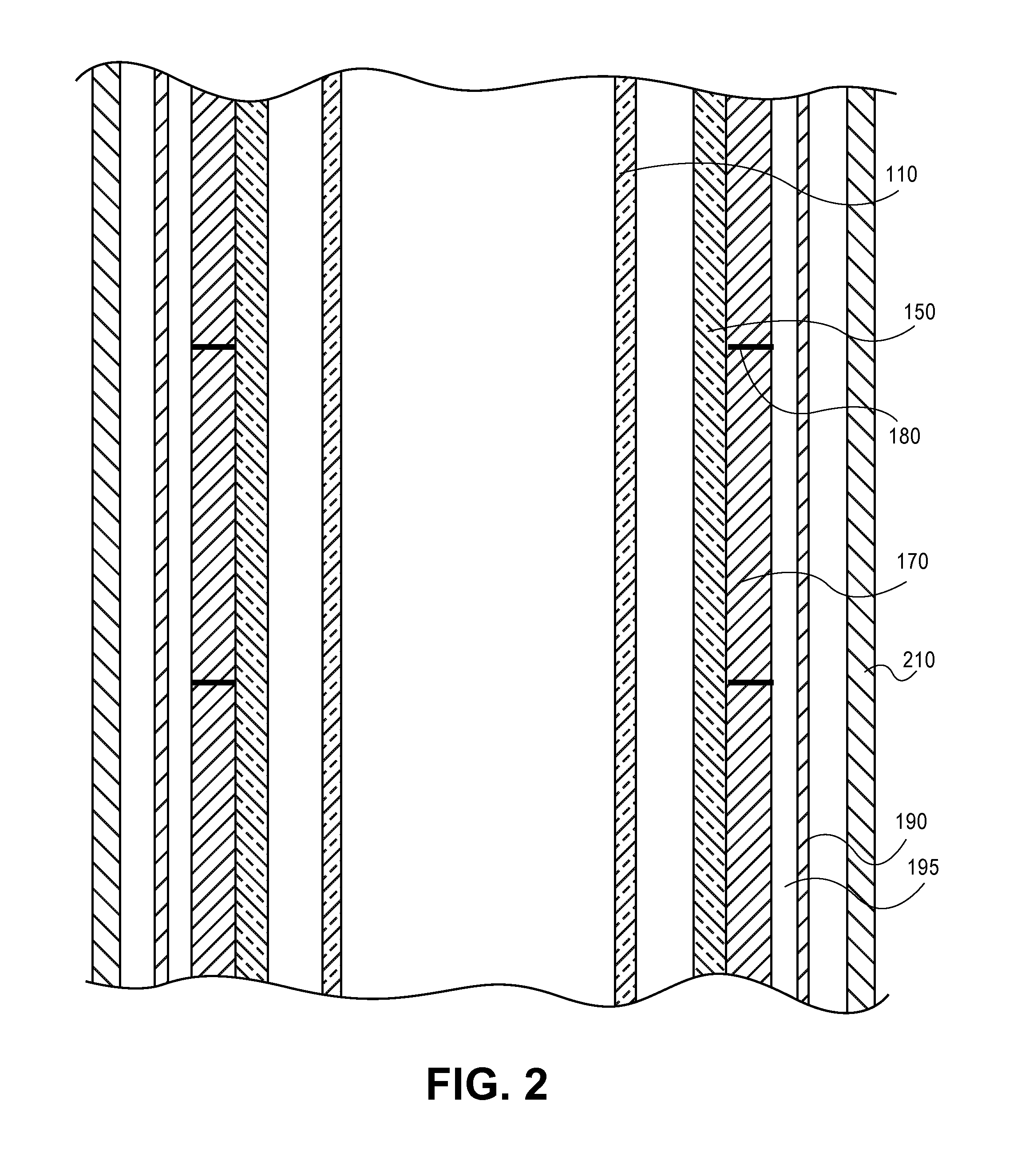
[0027]Piezoelectric means a material that changes its dimension in response to an applied voltage.

[0028]Production tubing is the piping that is connected segment by segment and placed in a well to enable fluid or gas insertion or extraction from the well.

Introduction

[0029]This invention addresses several technical problems presently extant with borehole seismic sources. First, this piezoelectric borehole source allows for permanent or semipermanent insertion into a well. This obviates the expensive and time consuming process of retrieving production tubing, lowering a temporary source into the well, taking measurements, and then replacing the production tubing. Second, this source allows for necessary tubing and electrical runs that pass along side of the production tubing to also pass through the piezoelectric borehole source. Third, the source is piezoelectric in nature, and can thereby be activated as needed on a continuous or intermittent basis by simple electrical ac...


PUM


Abstract

A piezoelectric borehole source capable of permanent or semipermanent insertion into a well for uninterrupted well operations is described. The source itself comprises a series of piezoelectric rings mounted to an insulative mandrel internally sized to fit over a section of well tubing, the rings encased in a protective housing and electrically connected to a power source. Providing an AC voltage to the rings will cause expansion and contraction sufficient to create a sonic pulse. The piezoelectric borehole source fits into a standard well, and allows for uninterrupted pass-through of production tubing, and other tubing and electrical cables. Testing using the source may be done at any time, even concurrent with well operations, during standard production.

Description

CROSS-REFERENCE TO RELATED APPLICATIONS[0001]This application claims the benefit of priority to PCT Application No. PCT / US2007 / 02940, which in turn claims priority to U.S. provisional application 60 / 863,914 filed Nov. 1, 2006, which applications are incorporated by reference in their entireties, as if fully set forth herein.STATEMENT REGARDING FEDERAL FUNDING[0002]This invention was made with U.S. Government support under Contract Number DE-AC02-05CH11231 between the U.S. Department of Energy and The Regents of the University of California for the management and operation of the Lawrence Berkeley National Laboratory. The U.S. Government has certain rights in this invention.BACKGROUND OF THE INVENTION[0003]1. Field of the Invention[0004]The present invention generally relates to the field of seismology, and more particularly to seismic sources, and most particularly to a piezoelectric borehole seismic source which may be emplaced into an active or inactive well in a permanent or semi...

Claims


Application Information

Patent Timeline
IPC IPC(8): G01V1/02
CPCB06B1/064G01V1/04G01V1/52G01V1/02
Inventor DALEY, TOM M.SOLBAU, RAY D.MAJER, ERNEST L.
Owner RGT UNIV OF CALIFORNIA
Why Eureka
Try Eureka