Eureka AIR delivers breakthrough ideas for toughest innovation challenges, trusted by R&D personnel around the world.

Single piece wheel set for a timepiece

a single-piece wheel and timepiece technology, applied in the field of single-piece wheel sets, can solve problems such as difficulty in manufacture, and achieve the effect of reducing inertia and reducing problems of alignmen

Active Publication Date: 2011-12-22
OMEGA SA
View PDF4 Cites 20 Cited by
  • Summary
  • Abstract
  • Description
  • Claims
  • Application Information

AI Technical Summary

Benefits of technology

It is an object of the present invention to overcome all of part of aforecited drawbacks by proposing a wheel set, such as for example a coaxial escape wheel set, wherein the problems of alignment are reduced and the inertia is decreased.
The invention therefore relates to a single piece wheel set including a first toothing formed at the periphery of a plate and a second toothing, wherein the second toothing is formed in a single piece with the plate of the first toothing so as to reduce any problems of alignment of one relative to the other and to decrease the overall mass of the wheel set and, in particular, a coaxial escape wheel set wherein the first toothing is arranged to cooperate with a pin and at least a first series of pallet-stones and a second toothing arranged to cooperate with a second series of pallet-stones.

Problems solved by technology

The design of this coaxial escapement requires very high precision, particularly as regards the relative alignment of the first 1 and second 11 escape wheels, which makes it difficult to manufacture.

Method used


Image

  • Single piece wheel set for a timepiece
  • Single piece wheel set for a timepiece
  • Single piece wheel set for a timepiece

Examples


first embodiment

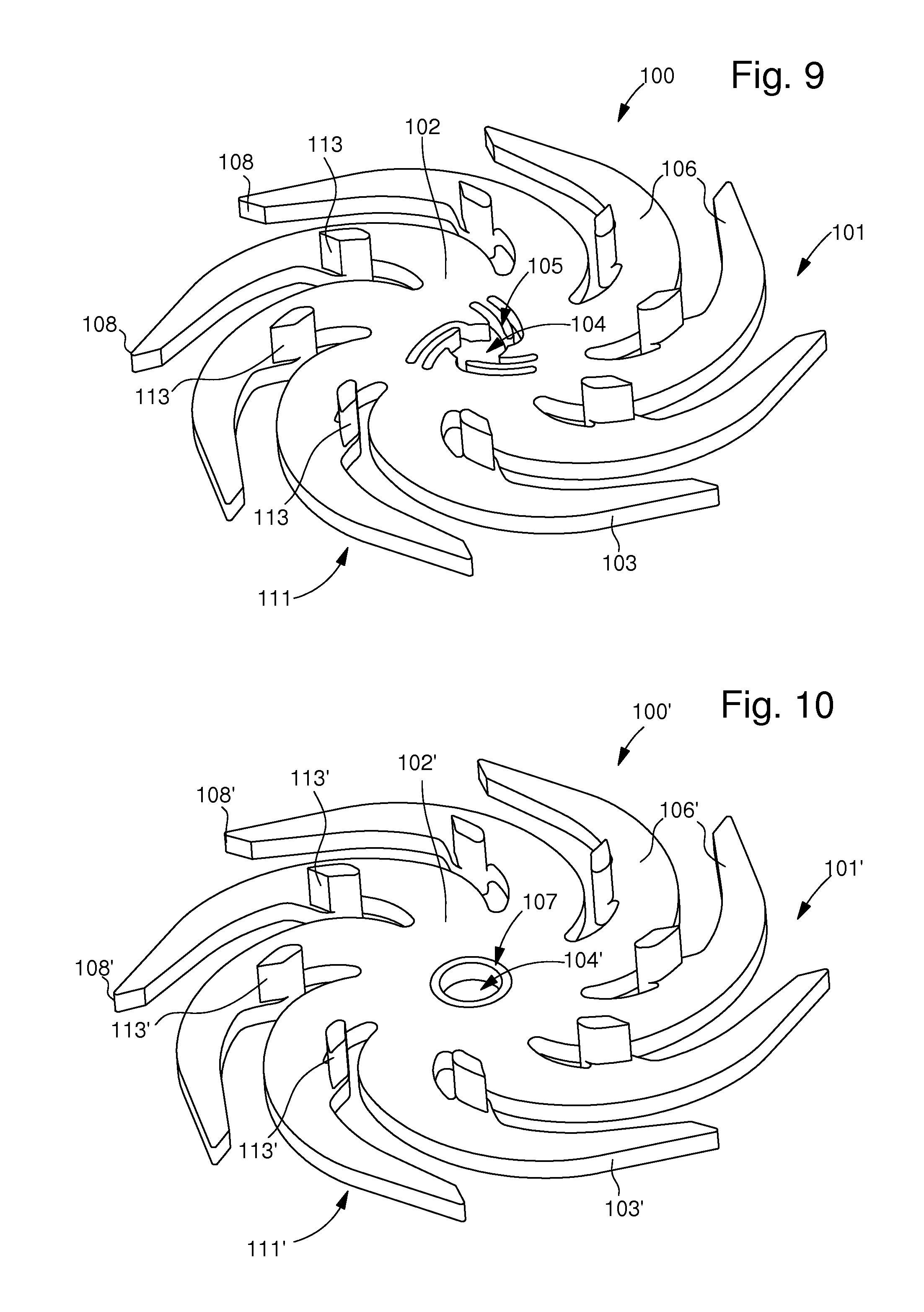
shown in FIG. 9, the first pattern forms a toothed wheel 101 corresponding to the first escape wheel 1 of FIG. 11. It includes a plate 103 forming a hub 102, the centre of which has an opening 104 and from which arms 106 start. The end of each arm forms a tooth 108 corresponding to a tooth 8 of FIG. 11. A plate 103 with a first toothing at the periphery thereof is thus obtained.

As illustrated in FIG. 9, opening 104 includes elastic securing means 105 intended to cooperate radially with an arbour of the type referenced 3 in FIG. 11, by elastic deformation, to rotatably mount escape wheel 101 and, consequently, escape wheel set 100. This elastic securing means 105 is formed by elongated parts made by hollowing out a portion of hub 102. The elongated parts enable the arbour to be gripped, i.e. wheel set 100 thereof to be secured, without subjecting the rest of plate 103 to any stress.

Of course, other elastic means may be envisaged. Such elastic means may, for example, take the form of ...

second embodiment

seen in FIG. 10, the first pattern forms a toothed wheel 101′ corresponding to the first escape wheel 1 of FIG. 11. It includes a plate 103′ forming a hub 102′ the centre of which has an opening 104′ and from which arms 106′ start, each end of said arms forming a tooth 108′ corresponding to a tooth 8 of FIG. 11. A plate 103′ including a first toothing at the periphery thereof is thus obtained.

As illustrated in FIG. 10, opening 104′ includes plastic securing means 107 intended to cooperate radially with an arbour of the type referenced 3 in FIG. 11, for rotatably mounting escape wheel 101′ and, consequently, escape wheel 100′. This plastic securing means 107 is formed by a washer made of metallic material allowing wheel set 100′ to be driven against said arbour via plastic deformation without subjecting plate 103′ to stress. Of course, other plastic securing means may be envisaged.

Thus, advantageously according to the invention, rather than adding a second escape wheel 11 as in FIG. ...


PUM


Abstract

The invention relates to a single piece coaxial escape wheel set (100, 100′) including a first toothing (108, 108′) formed at the periphery of a plate (103, 103′) and a second toothing (113, 113′). According to the invention, the second toothing (113, 113′) is formed in a single piece with the plate (103, 103′) of the first toothing (108, 108′) so as to reduce any problems of alignment of one in relation to the other and to decrease the overall mass of the wheel set (100, 100′).The invention concerns the field of timepieces.

Description

This application claims priority from European Patent Application No. 10166896.0 filed Jun. 22, 2010, the entire disclosure of which is incorporated herein by reference.FIELD OF THE INVENTION The invention relates to a single piece wheel set, for example a coaxial escape wheel set, and more specifically to a wheel set of this type made of micro-machinable or electroformable material.BACKGROUND OF THE INVENTIONIn a known manner, the escapement of a mechanical timepiece movement, whether it is coaxial or a Swiss lever escapement, includes an escape wheel wherein the regularly spaced teeth undergo the shock of pallet-stones which are generally made of ruby.An example of a coaxial escape system is presented in EP Patent No. 1 045 297. A mechanism of this type, as illustrated in FIG. 11, includes a wheel set formed of first 1 and second 11 escape wheels. The second escape wheel 11, also called an impulse pinion, is mounted on the same arbour 3. The angular position of teeth 13 of the sec...

Claims


Application Information

Patent Timeline
IPC IPC(8): G04B15/14G04B15/00
CPCG04B13/021G04B15/14G04B15/08
Inventor VAUCHER, FREDERICCUSIN, PIERREVERARDO, MARCOTHIEBAUD, JEAN-PHILIPPE
Owner OMEGA SA
Why Eureka
Eureka Blog
Learn More