
Use of substituted perylenes in organic solar cells

Inactive Publication Date: 2011-12-22
BASF AG
View PDF0 Cites 16 Cited by
  • Summary
  • Abstract
  • Description
  • Claims
  • Application Information

AI Technical Summary

Benefits of technology

[0019]It is an object of the invention to provide an organic sol

Problems solved by technology

Since the individual materials each make up only a portion of the mixed layer, the transport properties for the charge carriers additionally in many cases deteriorate significantly compared to the pure layers.
In addition, there are substance classes, for example particular oligothiophenes, which are surprisingly completely unsuitable for use in BHJ cells.
One possible cause might be that these molecules mix too well with the second semiconductor material used to produce the mixed layer and therefore do not form any percolation pathways.
However, there is currently still no demonstrable explanation.
It is therefore virtually unforeseeable whether a particular electron or hole conductor material is suitable at all, and certainly not whether it is advantageously suitable for use in an organic solar cell with photoactive donor-acceptor transitions in the form of a bulk heterojunction.

Method used


Image

  • Use of substituted perylenes in organic solar cells
  • Use of substituted perylenes in organic solar cells
  • Use of substituted perylenes in organic solar cells

Examples


examples

I. Preparation of Precursors

Example I.a

[0305]

[0306]7,9-Diphenyl-8H-cyclopenta[1]acenaphthylene-8-one was prepared according to Müllen et al. Chem. Eur. J. 2001, 7, 10 2197-2205. A mixture of 10.0 g (28 mmol) of 7,9-diphenyl-8H-cyclopenta[1]acenaphthylene-8-one, 9.8 g (52 mmol) of n-propyl-maleimide in 140 ml of chlorobenzene was heated at reflux for three hours. After cooling to room temperature, a solution of 5.8 g (37 mmol) of potassium permanganate and 9.7 mg (37 mmol) of 18-crown-6 was added. The mixture was heated at reflux for 2.5 hours. After cooling to approx. 120° C., the mixture was filtered and the residue was washed repeatedly with chlorobenzene. After cooling to room temperature, 9.70 g (74%) of the product were obtained from the filtrate.

example i.b

[0307]

[0308]0.41 g (0.9 mmol) of the compound obtained in example I.a was suspended in 30 ml of glacial acetic acid. To this were added 0.46 ml (9 mmol) of bromine and one grain of iodine. The mixture was stirred at 30° C. for 28 hours. Then another 0.12 ml (2.25 mmol) of bromine was added and the mixture was stirred at room temperature for six hours. Subsequently, the bromine was expelled by bubbling, and the residue was filtered off and washed with water and ethanol. This gave 362 mg (75%) of the title compound.

Example I.c

N-Phenyl-4-bromonaphthalene-1,8-dicarboxylic monoimide

[0309]

[0310]A mixture of 10.0 g (34 mmol) of 4-bromo-1,8-naphthalenedicarboxylic monoanhydride, 4.4 g (5.7 mmol) of aniline and 100 ml of propionic acid was heated to reflux overnight. After cooling to room temperature, the precipitate was filtered off with suction, washed with water and dried. This gave 10.1 g (68%) of the title compound as a colorless compound.

Example I.d

N-Phenyl-4-(pinacolatoboron)naphthale...

example i

[0337]

[0338]A mixture of 3.0 g (10.8 mmol) 4-bromo-1,8-naphthalic acid anhydride, 2.1 g (13.0 mmol) of 1,8-diaminonaphthalene, 1.99 g of zinc(II) acetate (10.8 mmol) and 300 ml of quinoline were refluxed at 145° C. for 5 hours. The reaction mixture was poured onto 500 mL of 1M hydrochloric acid. The precipitate was sucked off, washed with hot water and then crystallized from toluene to give 3.2 g (74%) of a violet-red compound.

[0339]Rf (dichloromethane)=0.80


PUM

PropertyMeasurementUnit
Nanoscale particle sizeaaaaaaaaaa
Temperatureaaaaaaaaaa

Abstract

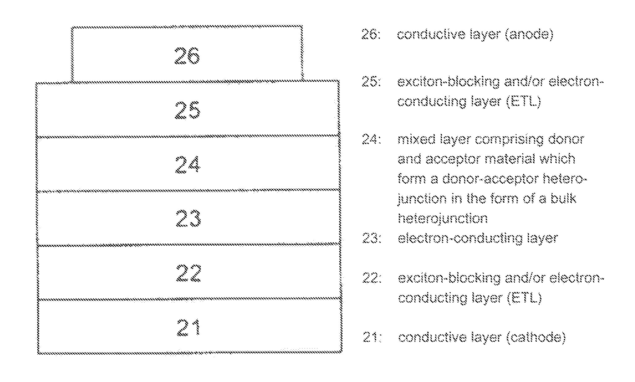
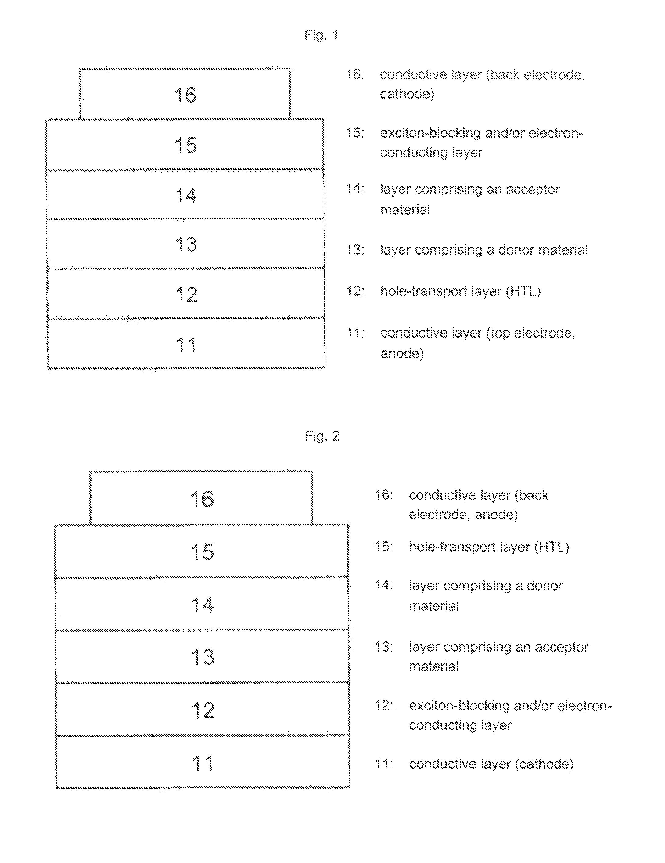
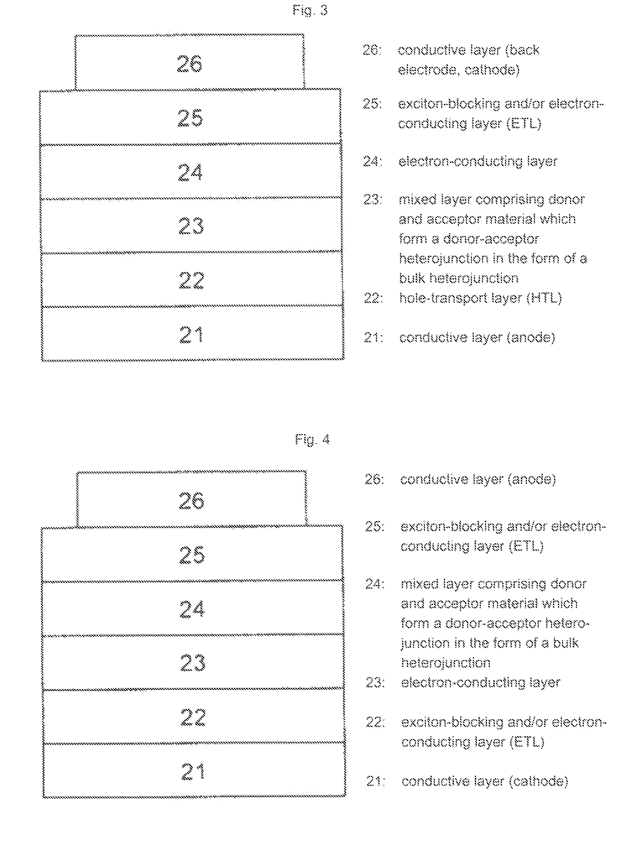
The present invention relates to an organic solar cell with a photoactive region which comprises at least one organic donor material in contact with at least one organic acceptor material, wherein the donor material and the acceptor material form a donor-acceptor heterojunction and wherein the photoactive region comprises at least one substituted perylene.

Description

BACKGROUND OF THE INVENTION[0001]The present invention relates to an organic solar cell with a photoactive region which comprises at least one organic donor material in contact with at least one organic acceptor material, wherein the donor material and the acceptor material form a donor-acceptor heterojunction and wherein the photoactive region comprises at least one substituted perylene.STATE OF THE ART[0002]Periflanthene derivatives, i.e. compounds with a diindeno[1,2,3-cd:1′,2′,3′-Im]perylene base skeleton:are the subject of intensive studies and have found use, for example, as chromophores and in systems based on electroluminescence, such as organic light-emitting diodes (OLEDs).[0003]The synthesis and the electroluminescence of dibenzotetraphenylperiflanthene is described by J. D. Debad, J. C. Morris, V. Lynch, P. Magnus and A. J. Bard in J. Am. Chem. Soc. 1996, 118, pages 2374-2379.[0004]M. Wehmeier, M. Wagner and K. Müllen describe, in Chem. Eur. J. 2001, 7, no. 10, p. 2197-2...

Claims


Application Information

Patent Timeline
IPC IPC(8): H01L51/46H01L31/06C07D487/04C07D221/18C07C13/62C07D209/56
CPCB82Y10/00C07C13/62C07C2103/54C07D209/70C07D221/18C07D333/18Y02E10/549C07D471/04H01L51/0046H01L51/0053H01L51/0056H01L51/424H01L51/4253C07D409/14C09B5/62C07C2603/54H10K85/211H10K85/621H10K85/624H10K30/20H10K30/30H10K30/50
Inventor KONEMANN, MARTINHWANG, JAE HYUNGMATTERN, GABRIELEHOH, REGINADORR, CHRISTIAN
Owner BASF AG
Learn More