
Adapter for Connecting a Countershaft Transmission with an Electric Hybrid System

a technology of electric hybrid and countershaft transmission, which is applied in the direction of battery/fuel cell control arrangement, transportation and packaging, etc., can solve the problems of increasing the size affecting the acceleration of the vehicle, and affecting the performance of the electric motor, etc., so as to overcome the problem of clutch wear, improve the acceleration of the vehicle, and transfer more power

Inactive Publication Date: 2011-12-15
EATON CORP
View PDF19 Cites 22 Cited by
  • Summary
  • Abstract
  • Description
  • Claims
  • Application Information

AI Technical Summary

Benefits of technology

This patent describes a way to attach a separate power source to a vehicle's wheels, which is especially useful for vehicles with a specific type of transmission. This invention also reduces wear and tear on the vehicle's clutch by eliminating the need to engage it when starting the vehicle. Additionally, it improves the vehicle's acceleration by using a supplemental motor to transfer power more quickly to the wheels than a traditional clutch engagement could alone.

Problems solved by technology

However, by placing the motor in line with the engine and transmission, increasing the size of the electric motor requires making many significant changes to the associated driveline components and mounting features at great expense.
At low speed operation, the torque converter losses are a much more significant portion of the power from the engine.
However, typical dry friction clutch plates or driven discs wear out undesirably quickly under such operating conditions.

Method used


Image

  • Adapter for Connecting a Countershaft Transmission with an Electric Hybrid System
  • Adapter for Connecting a Countershaft Transmission with an Electric Hybrid System
  • Adapter for Connecting a Countershaft Transmission with an Electric Hybrid System

Examples


Embodiment Construction

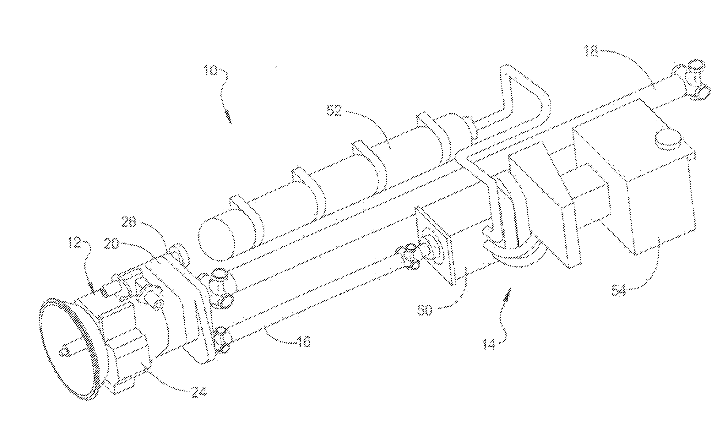
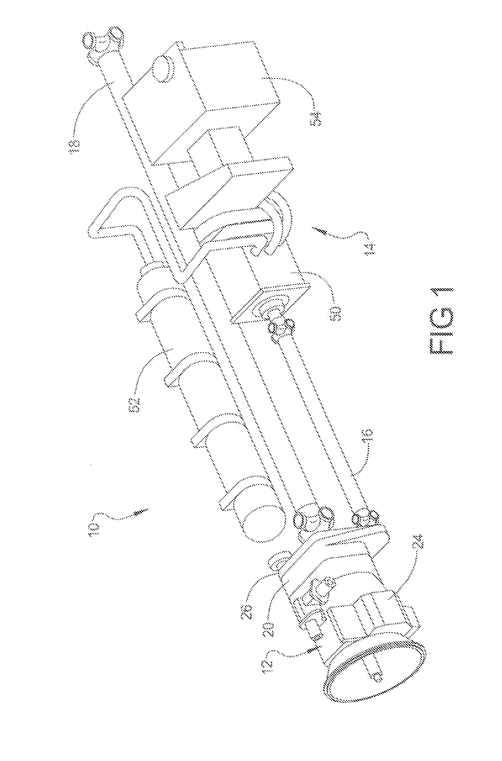
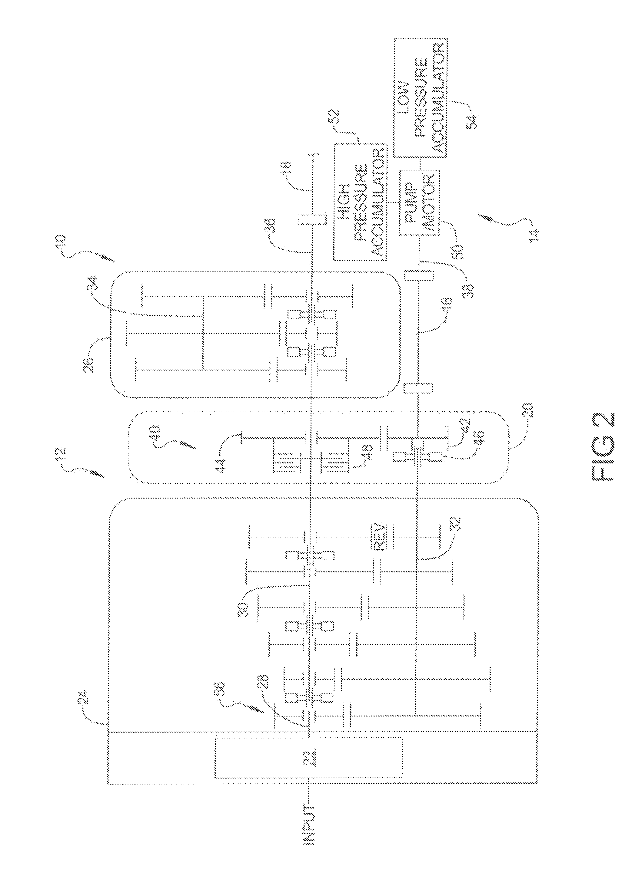
[0019]FIG. 1 shows a drivetrain 10 including an automated mechanical transmission (AMT) 12 connected to a hydraulic launch assist system (HLA system) 14 by an intermediate propeller shaft 16. Another propeller shaft, referred to hereafter as a driveshaft 18, is connected to transmission 12 on one end for connection to an axle (not shown) on the other end. An adapter module 20 is incorporated into transmission 12 to connect HLA system 14 to drivetrain. Adapter module 20 beneficially eliminates the need for a transfer case which was disposed between the transmission and the HLA system in prior art systems. Adapter module 20 provides much of the functionality of a transfer case with much less hardware. A master clutch 22 provides a selectively engaged driving connection between a vehicle drive engine (not shown) and AMT 12.

[0020]FIG. 2 shows schematically one configuration of the drivetrain of FIG. 1. Adapter module 20 is disposed between front box 24 and auxiliary section 26. The inve...


PUM


Abstract

This invention provides a common means of coupling an alternative power source to a vehicle's drive wheels which is particularly well suited for use with a countershaft-type transmission. This invention also addresses clutch wear by eliminating the need to engage the frictional clutch to launch the vehicle. This invention also improves the acceleration of the vehicle compared to a typical dry friction clutch launch by relying on a supplemental motor and associated control system to transfer more power to the drive wheels more quickly than would be transferred by a typical launch engagement of a dry friction clutch in a commercial vehicle.

Description

CROSS-REFERENCE TO RELATED APPLICATIONS[0001]This application claims the benefit of U.S. Provisional Application No. 61 / 353,860, filed Jun. 11, 2010, and U.S. patent application Ser. No. 12 / 943,044, filed Nov. 10, 2010 which are hereby incorporated by reference in their entireties.BACKGROUND OF THE INVENTION[0002]Known hybrid vehicle drive systems coupling an internal combustion engine and an alternative power source such as an electric motor or a hydraulic motor require means of linking the alternative power source and the internal combustion engine to the drive wheels. Each configuration may have a preferred configuration, but such configuration can vary with vehicle use and application.[0003]One known electric hybrid system, of the general type described in U.S. Pat. No. 7,463,962, has an electric motor coupled to a transmission input shaft. This configuration was well suited for use with a transmission having a countershaft powerflow configuration. However, by placing the motor ...

Claims


Application Information

Patent Timeline
Patent Type & Authority Applications(United States)
IPC IPC(8): F16H37/06F16H3/00
CPCB60K6/12Y10T74/19051B60K6/48B60L11/14B60L11/1853F16H3/0915Y02T10/6208Y02T10/6221Y02T10/6282Y02T10/7005Y02T10/705Y02T10/7077Y02T10/70Y10T74/19223B60K6/387B60L50/16B60L58/18Y02T10/62Y02T10/7072B60K2006/4825B60K2006/4816B60K2006/4833B60K2006/4808
Inventor GENISE, THOMAS A.
Owner EATON CORP
Learn More