
Free radical injection ionizer for flue gas treatment with corona discharge

a free radical injection and flue gas treatment technology, applied in the field of waste gas treatment, can solve the problems of large process energy consumption, high energy consumption, energy waste, etc., and achieve the effect of reducing cost, effective solving problems, and high energy consumption

Inactive Publication Date: 2011-12-08
GAO XIANG +15
View PDF11 Cites 4 Cited by
  • Summary
  • Abstract
  • Description
  • Claims
  • Application Information

AI Technical Summary

Benefits of technology

[0008]The invention incorporating good flue gas treatment effect, low energy consumption and small equipment investment provides a free radical injection ionizer for flue gas treatment with corona discharge to solve the problems of poor flue gas treatment effect, high energy consumption and large equipment investment of the current devices for flue gas treatment with non-thermal equilibrium plasma techniques.
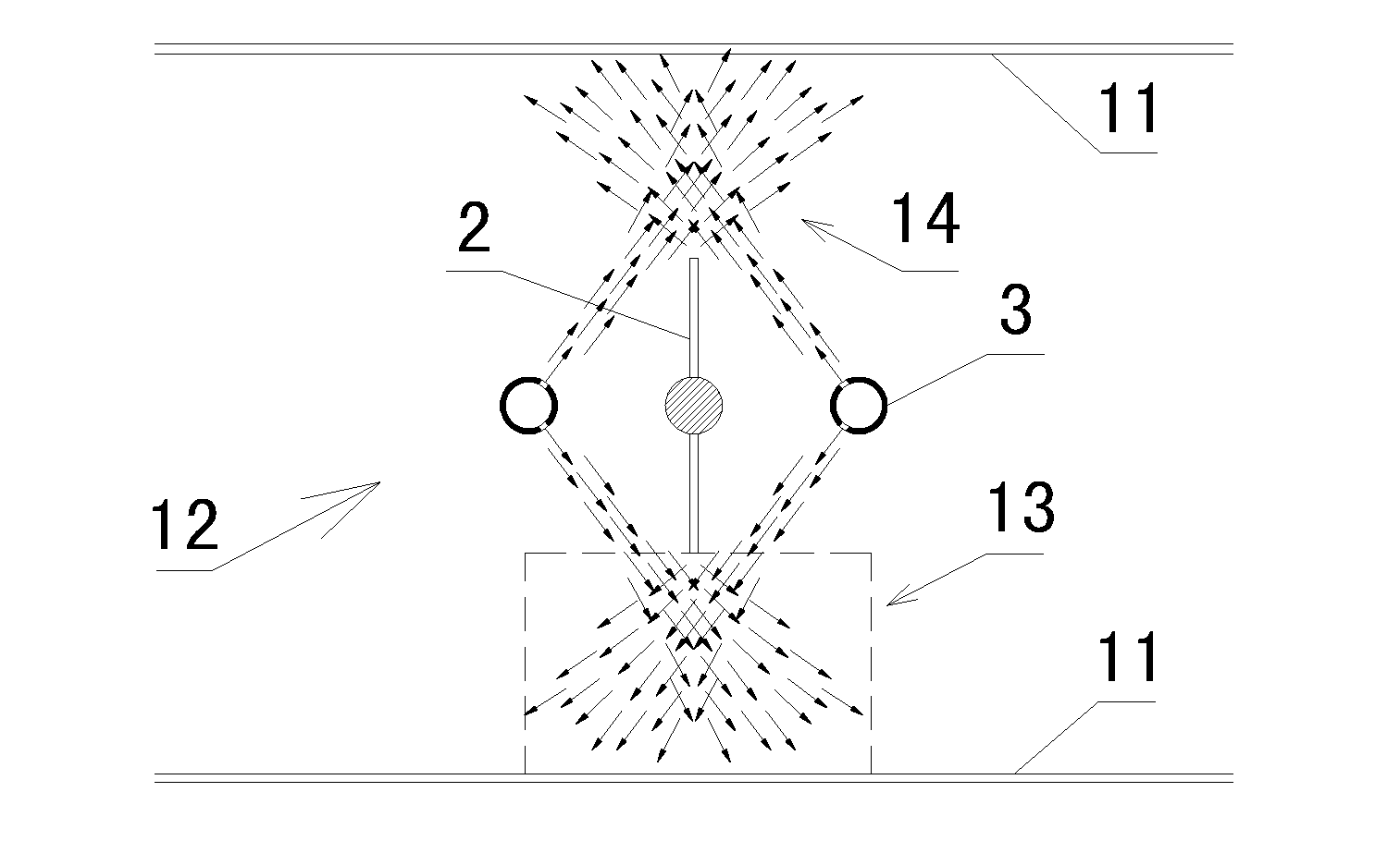
[0009]To achieve the technical purpose above, the invention adopts the specific technical scheme: a free radical injection ionizer for flue gas treatment with corona discharge arranged in a flue gas channel and comprising an injection device for releasing free radical source substances and a separately arranged electrode device for producing corona. The electrode device comprises a conductive pole, and discharge tips arranged on the upper and lower sides of the conductive pole at equal intervals. The injection device comprises nozzles symmetrically arranged on two sides of the electrode device, and two lines of holes axially arranged on the wall of the nozzles nearby the electrode device. The holes are arranged at equal intervals with each other and with the discharge tips, and the axial lines of the holes direct the discharge tips nearest the holes. The injection device and electrode device are separately arranged and the axial lines of the holes direct the discharge tips nearest the holes, so that the free radial source substances sprayed out from the insulated nozzles on two sides of the electrodes are crosswise mixed with larger distribution zones. The experimental result of the free radical source substance discharge zone is shown in FIG. 8, from which it can be seen that, compared with the prior art, the free radical source substance discharge zone is larger and more well-distributed. Although the ionization degree of the free radical source substances nearby the discharge ends of the electrodes is possibly lower than that at the nozzle tips of the nozzle structure, on the whole, the free radicals produced by the free radical injection ionizer of the invention widely contact with the flue gas, so that the removal efficiency of the flue gas is higher, and the whole effect is obviously better than that of the discharge electrode of the nozzle structure. In addition, in the circumstance of the same flue gas treatment effect, the structure of the invention is obviously capable of reducing the electrode quantity, so as to considerably reduce the energy consumption; moreover, the structure of the invention requires no hollow nozzles on two sides of one electrode, and is simply structured, so as to effectively reduce the production cost. The method is adaptive to the direct current corona discharge as well as the pulse corona process.
[0011]As a preferred embodiment, the holes are provided with flexible guiding hoses whose outlets are provided with well-distributed radial apertures. The holes are provided with flexible guiding hoses in the injection directions thereof, so that the flexible guiding hoses will irregularly wave or shake under the action of the flow injected from the holes. The flexible guiding hoses are provided with well-distributed radial apertures at the outlets thereof, so that the irregular waving or shaking may be further enhanced, upon which, the free radical source substances injected from the flexible guiding hoses have a larger range, and also the free radicals produced after the ionization of the free radical source substances have a larger distribution range to contact with more flue gas and improve the flue gas treatment effect.
[0013]As a preferred embodiment, the discharge tips are serrated sharp and are symmetrical settled on the upper and lower sides of the conductive pole which is structured like a plate, and integrally formed with the conductive pole. The vertex angle of the serrated structure is 40-50 degrees. The serrated electrode is one of the common electrodes in electrostatic precipitators, so that the invention may further reduce cost, and implement the integral dust precipitation and purification by combining with electrostatic precipitators.
[0015]As a preferred embodiment, one end of one nozzle is a sealed end connected with a vibrator through a connecting rod, and the other end of the nozzle is connected with a free radical air source through a hose. The action of connecting one end of the nozzle with the vibrator is similar as that of arranging the flexible guiding hose on the holes of the nozzles, but the vibrator may change the injection direction or range of the free radical source substances by controlling the vibration amplitude, direction or frequency of the nozzles to make the whole flue gas treatment device reach the optimum treatment effect.
[0016]The invention has the advantages of effectively solving the problems of poor flue gas treatment effect, high energy consumption and large equipment investment existing in the current devices for the flue gas treatment with non-thermal equilibrium plasma techniques. It has simple structure, good flue gas treatment effect, low energy consumption, and capability of combining with electrostatic precipitators to implement the integral dust precipitation and purification.

Problems solved by technology

However, the main gas molecules in the high-energy electron pair flue gas produced from the electron beam process can break down the chemical bonds thereof, and decompose and ionize gas molecules with high content, such as N2 and CO2, in the flue gas, causing energy waste and large energy consumption in the process.
Furthermore, the problems of expensive electron gun, shot longevities of electron gun and target window, complex equipment structure, large space, ammonia escape, shielding and protection of X-ray and the like are existing.
The energy consumption of the pulse corona process was only 50% of that of the electron beam process, but the pulse corona process still took effect and apply to ionize gas molecules, such as N2 and CO2, in the flue gas, resulting in energy waste.
In addition, during the actual application of the electron beam process or pulse corona process, ammonia gas is usually added as absorbent and incapable of complete reaction, resulting in leakage and pollution to the surroundings after being discharged into the air.
In the pulse and direct current corona discharge pollutants removal systems, if the conventional discharge electrode structures are used, such as wire-cylinder structure and wire-plate structure, the corona zone of flue gas direct current corona discharge is smaller and only limited to the proximity of wire electrodes, and the discharge current is weaker, so that the pollutants removal effect is poor.
If multi-pin and one-plate discharge structure is used, although the corona discharge zone and discharge current are increased, the energy consumption is larger.
If the electrodes are arranged more densely, the energy consumption of the system will be considerably increased.
In addition, such hollow electrode is difficult to process and has high cost, upon which the investment on the equipment for engineering application will be obviously increased.

Method used


Image

  • Free radical injection ionizer for flue gas treatment with corona discharge
  • Free radical injection ionizer for flue gas treatment with corona discharge
  • Free radical injection ionizer for flue gas treatment with corona discharge

Examples


embodiment 1

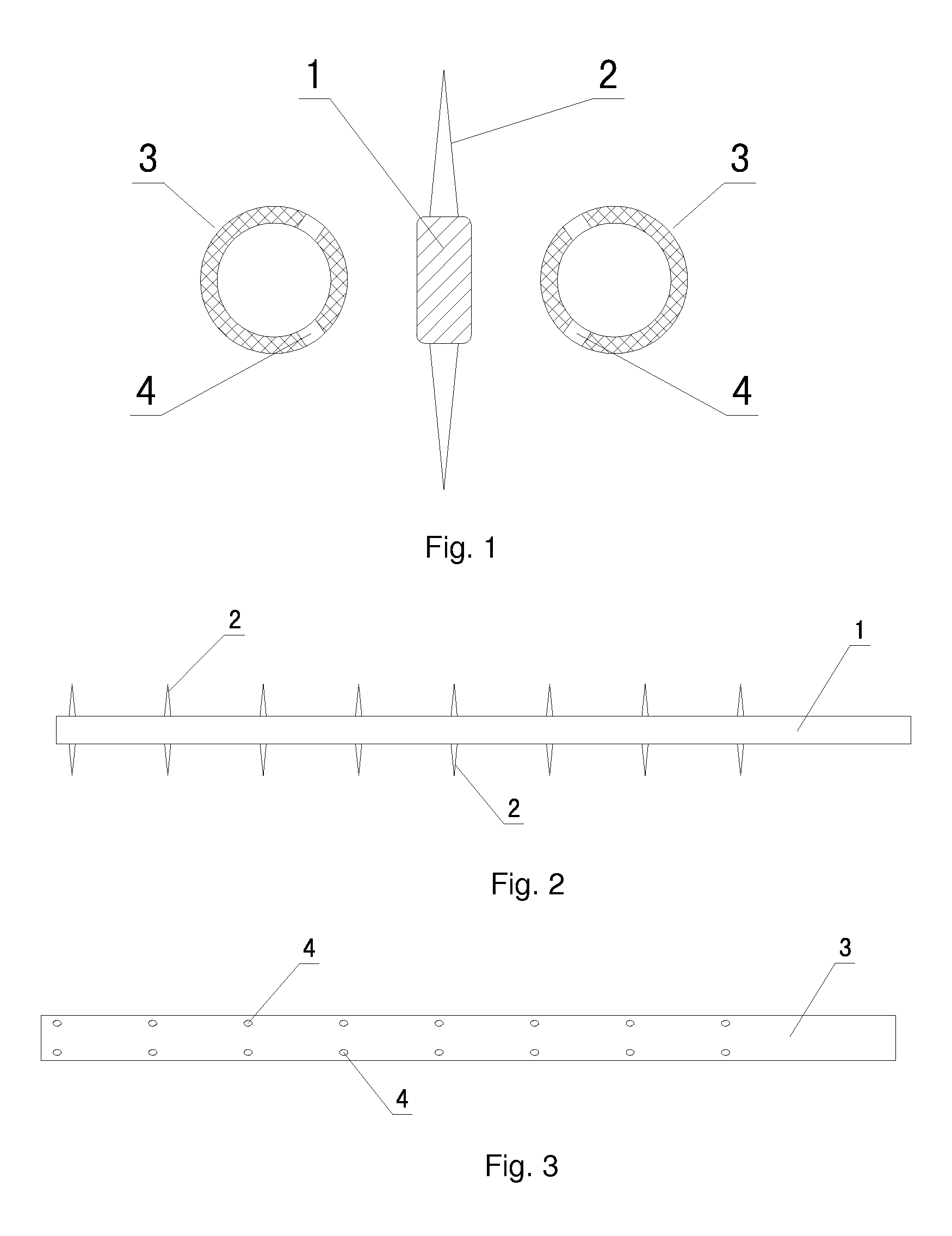
[0026]In Embodiment 1 shown as FIG. 1, a free radical injection ionizer for the corona discharge flue gas treatment arranged in a flue gas channel in which the electrode plates are arranged on the upper and lower sides of the flue gas channel, comprising an injection device for releasing free radical source substances and an electrode device for producing corona. The injection device and the electrode device are separately arranged. The electrode device comprises a conductive pole 1, and conical discharge tips 2 arranged on the upper and lower sides of the conductive pole at equal intervals. The ratio of the intervals of the discharge tips to the length of the discharge tips is 3 to 1, and there are eight discharge tips on each line of the conductive pole (see FIG. 2). The injection device comprises nozzles 3 symmetrically arranged on two sides of the electrode device and connected with a free radical air source, in which the diameter of the nozzles is less than the total height of ...

embodiment 2

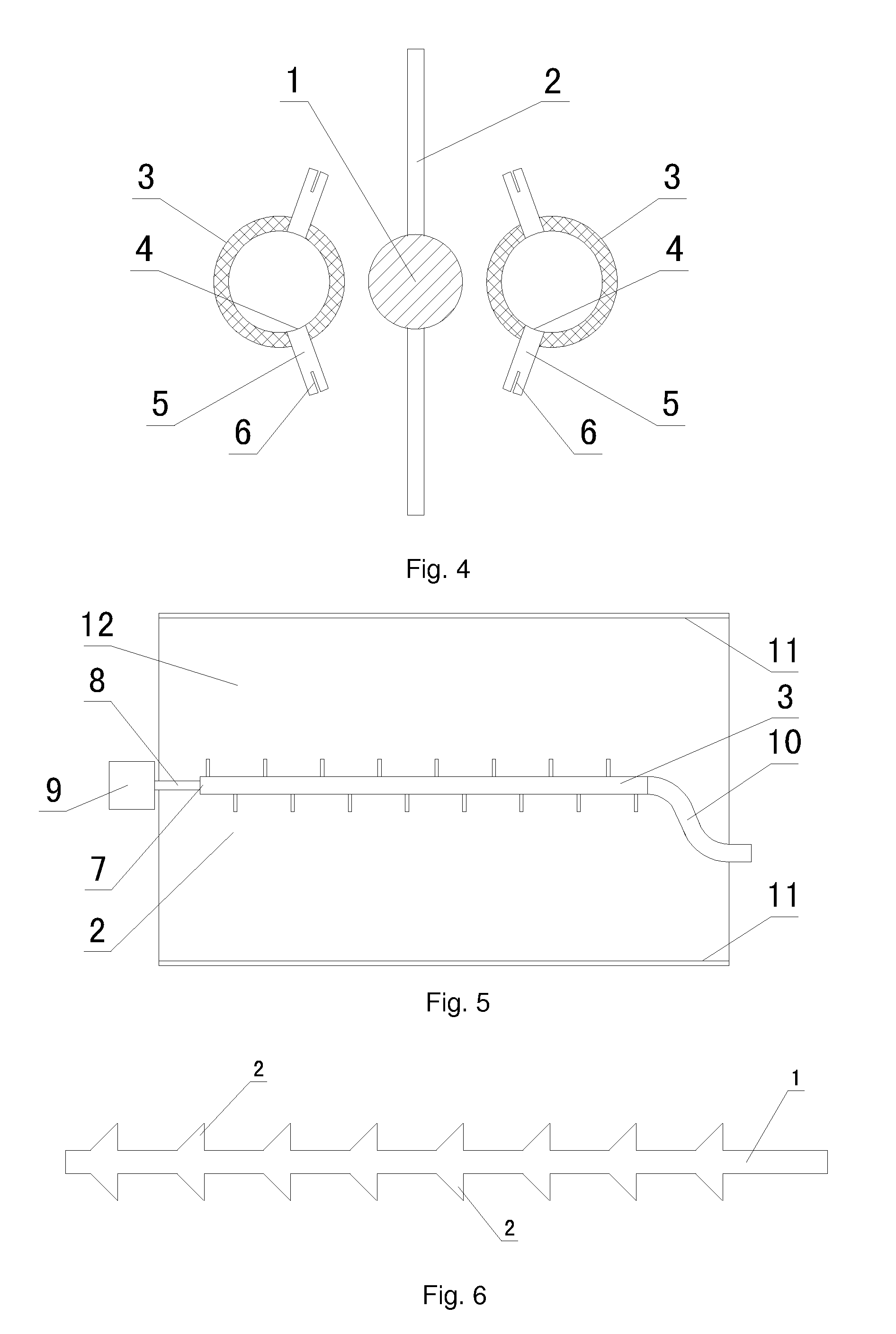
[0027]The discharge tips of Embodiment 2 are cylindrical (see FIG. 4). The ratio of the intervals of the discharge tips to the length of the discharge tips is 5 to 1, and there are twelve discharge tips on each line of the conductive pole. The holes are provided with flexible guiding hoses 5 whose outlets are provided with well-distributed radial apertures 6. The rest of the embodiment is the same as Embodiment 1.

embodiment 3

[0028]The discharge tips on the upper and lower sides of the conductive pole of Embodiment 3 are staggered (see FIG. 5). The holes on the nozzles are staggered, and are adapted to the discharge tips. One end of the nozzle is a sealed end 7 connected with a vibrator 9 through a connecting rod 8, and the other end of the nozzle is connected with a free radical air source through a hose 10. The rest of the embodiment is the same as Embodiment 1.


PUM


Abstract

A free radical injection ionizer for flue gas treatment with corona discharge comprises an injection device for releasing free radical source substances and an electrode device for producing corona, wherein the injection device and the electrode device are arranged separately, wherein the electrode device comprises a conductive pole, and discharge tips arranged on the upper and lower sides of the conductive pole at equal intervals, and the injection device comprises nozzles symmetrically arranged on two sides of the electrode device, and two lines of holes axially arranged on the walls of the nozzles nearby the electrode device, the axial lines of the holes directing the discharge tips nearest the holes.

Description

FIELD OF THE INVENTION[0001]The invention relates to the technical field of waste gas treatment, and in particular, to a free radical injection ionizer for flue gas treatment with corona discharge.BACKGROUND OF THE INVENTION[0002]The technique for simultaneously removing flue gas pollutants by the non-thermal equilibrium plasma is one of the most promising comprehensive flue gas treatment techniques currently, which uses particles with high reactivity produced from gas discharge to react with various organic and inorganic pollutant molecules which are thereby decomposed and oxidized into harmless substances or easily treatable compounds. This technique has the characteristic of effectively, conveniently and non-selectively decomposing various pollutants by using simple equipment and small space, therefore it is adaptive to various working environments, and as a result, the application of non-thermal equilibrium plasma technique for simultaneously controlling pollutants in flue gas h...

Claims


Application Information

Patent Timeline
IPC IPC(8): B03C3/41
CPCB01D2259/818B01J19/088B01J2219/083B01J2219/0849B01J2219/0869H05H2001/483H01T23/00H05H1/24H05H1/48H05H2001/2425B01J2219/0875B03C3/41B03C2201/06B03C2201/08B03C2201/10H05H1/471
Inventor GAO, XIANGLUO, ZHONGYANGCEN, KEFANI, MINGJIANGWU, ZULIANGZHONG, YIZHANG, YONGXINXU, DIANWU, WEIHONGSHI, ZHENGLUNZHOU, JINSONGFANG, MENGXIANGYU, CHUNJIANGWANG, SHURONGCHENG, LEMINGWANG, QINHUI
Owner GAO XIANG
Learn More