
System and method for carbon dioxide capture and sequestration

a carbon dioxide and sequestration technology, applied in the field of systems and methods for removing greenhouse gases from an atmosphere, can solve the problems of negative carbon, 300 times more expensive, and no sense in using ambient air as opposed to flue gas, and achieve the effect of low cos

Active Publication Date: 2011-12-08
GLOBAL THERMOSTAT OPERATIONS LLC
View PDF0 Cites 109 Cited by
  • Summary
  • Abstract
  • Description
  • Claims
  • Application Information

AI Technical Summary

Benefits of technology

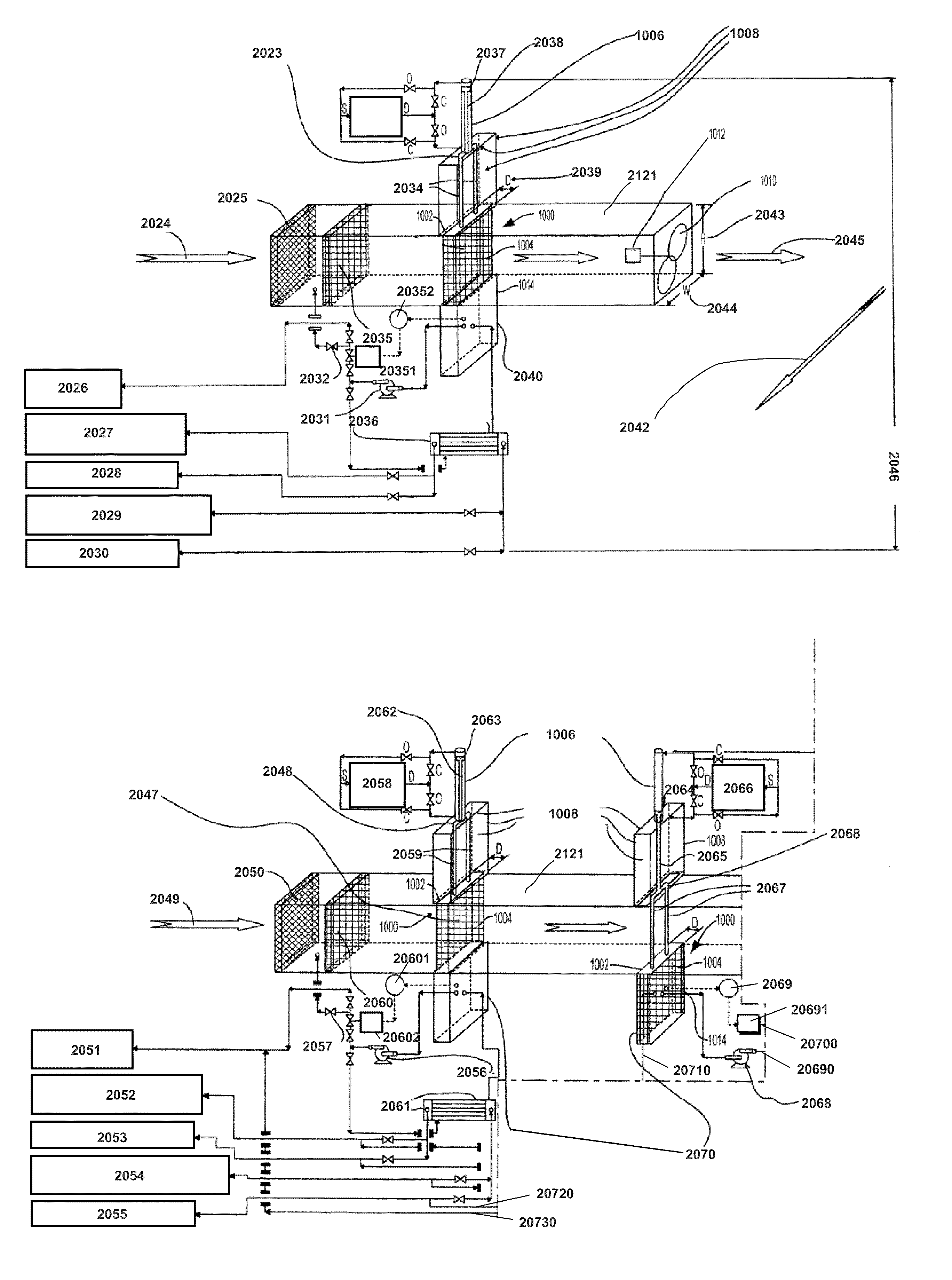
[0010]Moreover, in another of its aspects, this application provides some additional structures and techniques that can be used to capture carbon dioxide from carbon dioxide laden air, and using process heat to separate carbon dioxide from a sorbent and regenerate the sorbent, and which further enables the carbon dioxide separation and regeneration to be practiced directly in line with a source of flue gases that would otherwise emanate directly from that source and direct carbon dioxide laden air into the atmosphere.
[0011]In addition, this invention provides a relatively low cost and relatively pure CO2 source for such beneficial uses as feeding algae farms for biofuel production, where the capture costs represents the entire cost of the CO2 supply.

Problems solved by technology

In the former case it goes directly against conventional wisdom that 300 times lower concentration of the CO2 in ambient atmosphere would expect it to be 300 times more expensive since separation costs are thought to generally scale inversely with the concentration.
Thus most efforts have been directed at extracting CO2 from the flue gas emissions of power plants (e.g. clean coal) and experts have publicly claimed that the use of ambient air as opposed to flue gas makes no sense.
In addition, the applicants' approach would produce negative carbon, actually reducing the amount of CO2 in the atmosphere, while cleaning up the flue gas would only prevent the CO2 content in the air from increasing.
Further analysis shows that one cannot solve the global warming problem in a timely manner to reduce the great risk it poses by simply cleaning up large stationary fossil fuel sources like coal plants or for that matter by conservation or use of renewables.
Other published schemes for extracting CO2 from the ambient atmosphere have used higher temperature heat generally and not process heat specifically and therefore have not been seriously considered because of their high energy costs.
In the former case, the only driving force for desorption is thermal, and the significant gas phase CO2 pressure severely limits how much CO2 will desorb.
In other work, higher temperature inert gas temperature swing desorption, stability was less than what would be desired during multiple regeneration cycles with Class 1 adsorbents.
It might be anticipated that these materials could be the least stable of the three classes of adsorbents under steam-stripping conditions, due to the lack of covalent bonds between the aminopolymer and the support and the measurable solubility of low molecular weight PEI in water.
During the past history of our planet, for example, there have been many periods of glaciation and rapid temperature swings that have caused destruction and even mass extinctions.
Such temperature swings in the future could be a direct cause of massive damage and destabilization of human society from conflicts resulting from potential diminished resources.

Method used


Image

  • System and method for carbon dioxide capture and sequestration
  • System and method for carbon dioxide capture and sequestration
  • System and method for carbon dioxide capture and sequestration

Examples


Embodiment Construction

Background Description of the System and Method Concepts of application Ser. No. 12 / 124,864

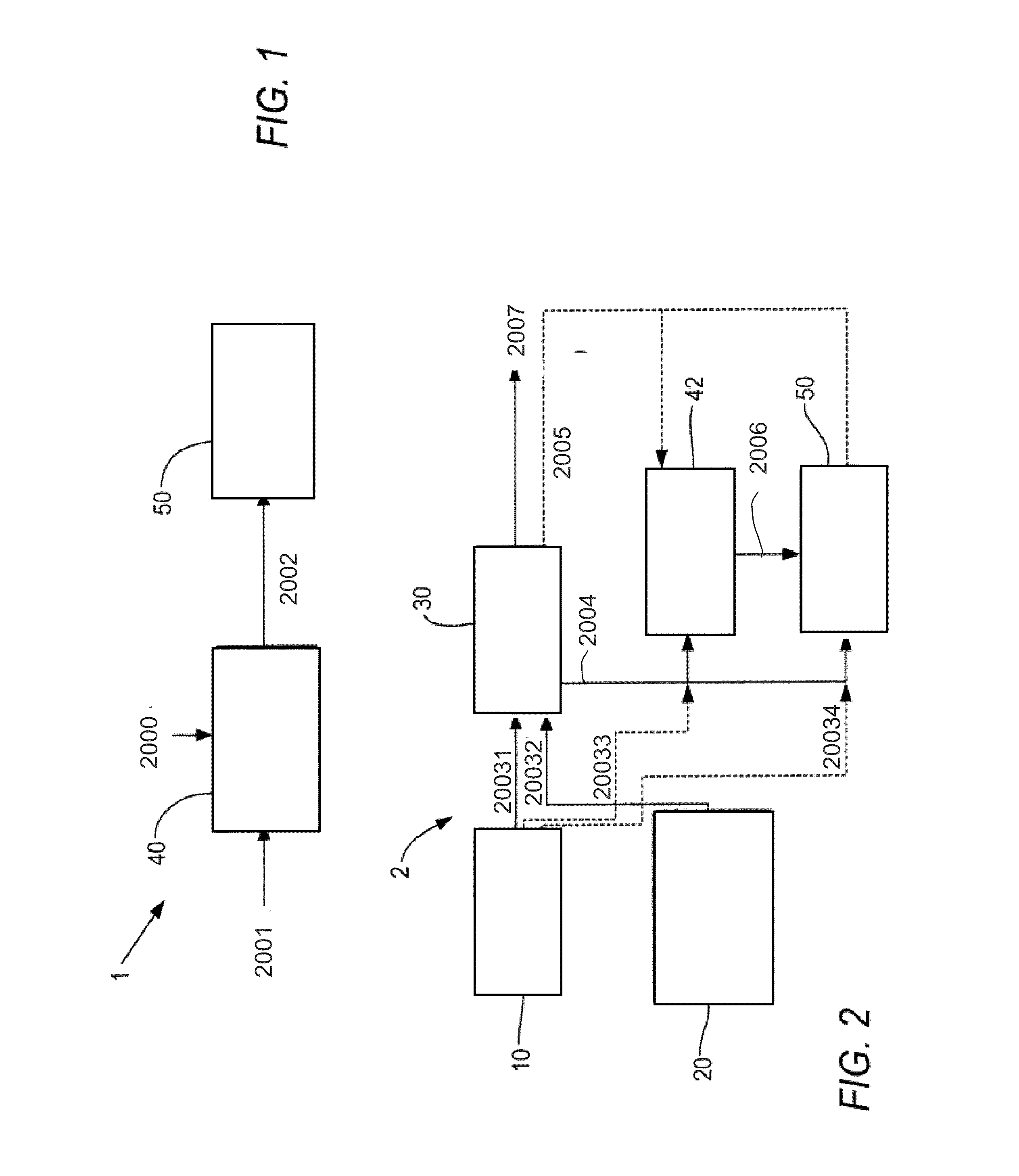
[0033]Initially, it is believed useful to describe the method and system of U.S. application Ser. No. 12 / 124,864, to provide background for the additional ways the present invention further develops those principles. FIGS. 1-9 illustrate the system and method of U.S. application Ser. No. 12 / 124,864. FIG. 1 is a generalized block diagram of a system, generally designated by reference number 1, for removing carbon dioxide from an atmosphere according to an exemplary embodiment of the present invention. The system 1 includes an air extraction system 40 and a collection system 50 that isolates the removed carbon dioxide to a location for at least one of sequestration, storage and generation of a renewable carbon fuel or the generation of a non-fuel product such as fertilizer and construction materials (or to be used in green houses or to enhance the rate of microbial production of biofuels). The a...


PUM

PropertyMeasurementUnit
Temperatureaaaaaaaaaa

Abstract

A method and a system capable of removing carbon dioxide directly from ambient air, and obtaining relatively pure CO2. The method comprises the steps of generating usable and process heat from a primary production process;applying the process heat from said primary process to water to co-generate substantially saturated steam, alternately repeatedly exposing a sorbent to removal and to capture and regeneration system phases, wherein said sorbent is alternately exposed to a flow of ambient air during said removal phase, thereby enabling said sorbent to sorb, and therefore remove, carbon dioxide from said ambient air, and to a flow of the co-generated steam during the regeneration and capture phase, after the sorbent has adsorbed the carbon dioxide, thereby enabling regeneration of such sorbent, and the resultant capture in relatively pure form of the adsorbed carbon dioxide. This process can also be carried out in more efficient form by admixing with the air a minor amount of a flue gas or an effluent gas containing a higher concentration of carbon dioxide than exists in the atmosphere, most preferably following a pre-treatment. The carbon dioxide can be stored for further use, or sequestered permanently following the capture: The adsorbent is exposed to air at substantially ambient conditions and the adsorbent is exposed to the co-generated steam at a temperature in the range of not greater than about 130° C. The system provides the sorbent substrate and equipment for carrying out the above method, and provides for obtaining purified carbon dioxide for further use in agriculture and chemical processes, including manufacturing hydrocarbon fuels, or for permanent sequestration, as needed.

Description

[0001]The application claims the benefit or priority pursuant to 35 U.S.C. 119(e) from a U.S. Provisional Patent Application having Application No. 61 / 330,108 filed Apr. 30, 2010; from a U.S. Provisional Patent Application having Application No. 61 / 351,216 filed Jun. 3, 2010 and from a U.S. Provisional Patent Application having Application No. 61 / 443,061 filed Feb. 15, 2011.BACKGROUND[0002]The present invention relates to systems and methods for removing greenhouse gases from an atmosphere, and in particular to systems and methods for removing carbon dioxide from an atmosphere.U.S. application Ser. No. 12 / 124,864[0003]As explained in U.S. application Ser. No. 12 / 124,864,[0004]a. there is much attention currently focused on trying to achieve three energy related and somewhat conflicting energy related objectives: 1) provide affordable energy for economic development; 2) achieve energy security; and 3) avoid the destructive climate change caused by global warming. However, there is no...

Claims


Application Information

Patent Timeline
IPC IPC(8): B01D53/02F25J3/08B01D53/30C01B32/50
CPCB01D53/04B01D53/62B01D2251/304B01D2251/604B01D2257/504B01D2258/06Y02C10/04Y02C10/08F01N3/0857B01J20/28042B01D53/08B01D2259/4009B01J20/08B01J20/103B01J20/22B01J20/3425B01J20/3466B01J20/262B01J20/28016B01J20/28097B01D53/0462Y02P20/151Y02C20/40Y02A50/20B01D53/81B01D2252/204B01D53/82B01D53/83B01D53/96B01D2253/106B01D2253/20B01D2253/25B01D2253/104
Inventor EISENBERGER, PETER
Owner GLOBAL THERMOSTAT OPERATIONS LLC
Learn More