
Electron tube with optimized injection of the electron beam into the tube

a technology of electron beam and electron beam, which is applied in the direction of transit tubes/containers, cathode ray tubes/electron beam tubes, electric discharge tubes, etc., can solve the problems of concentricity defects, failure and failure to make it possible to correct concentricity defects and parallelism of beam axes

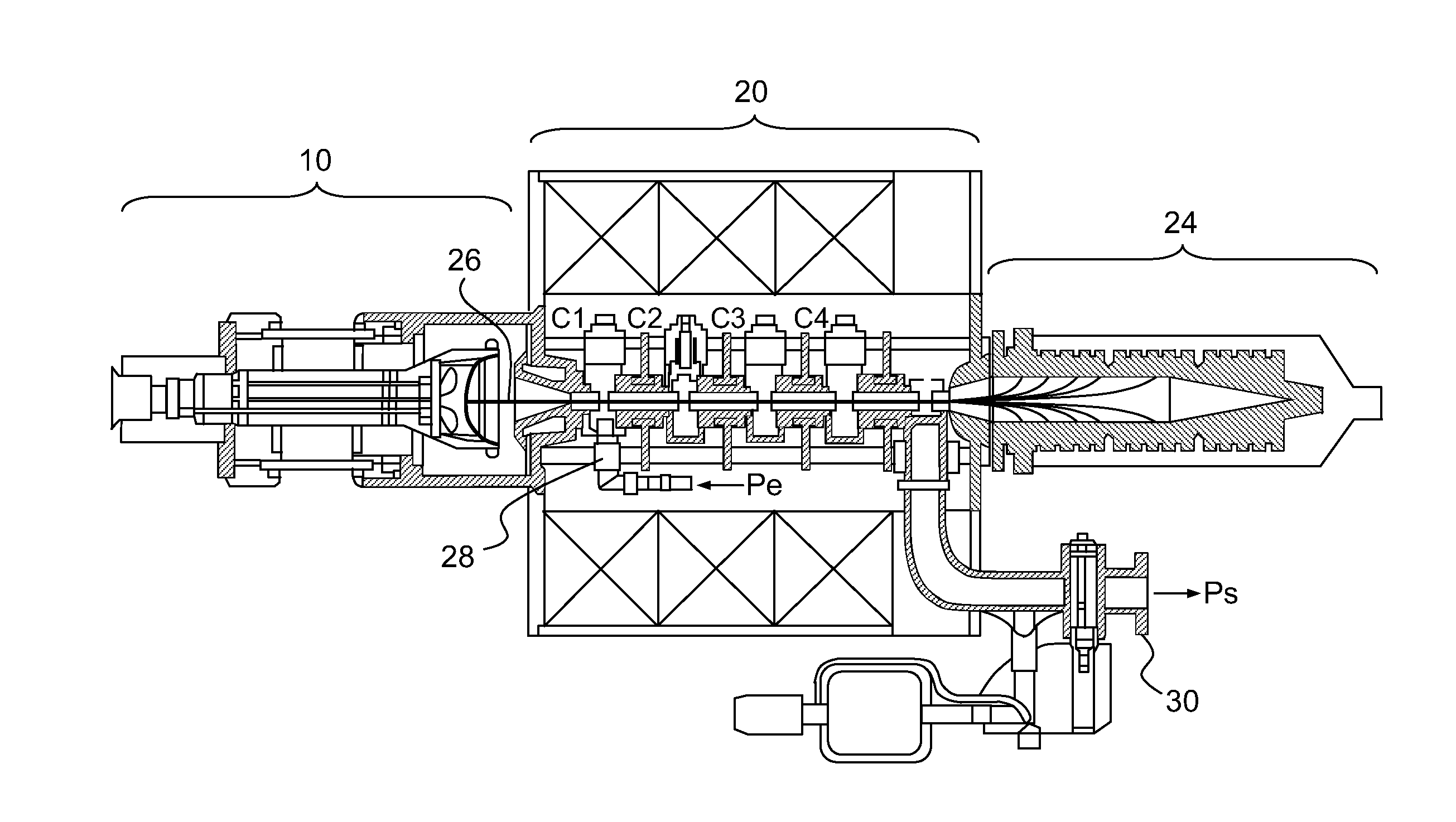
Inactive Publication Date: 2011-12-01
THALES SA
View PDF0 Cites 5 Cited by
  • Summary
  • Abstract
  • Description
  • Claims
  • Application Information

AI Technical Summary

Benefits of technology

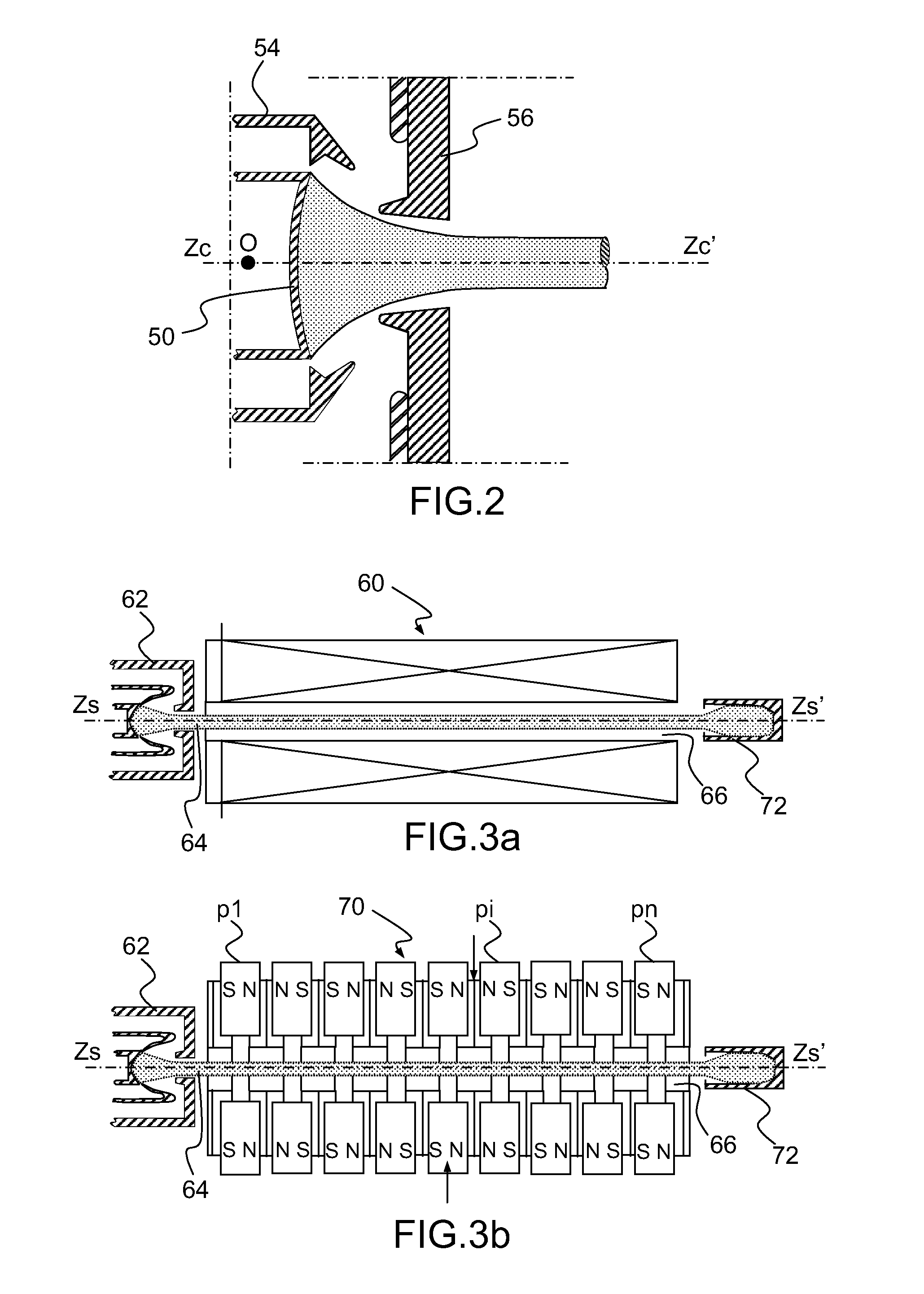
[0042]In one embodiment of the tube, the end of the circular envelope in proximity to the microwave structure is prolonged by a tubular wall, coaxial with the axis of the circular envelope of the gun and secured to the said end of the circular envelope, the tubular wall comprising, on the side of its free end, a setup ring having an external circular surface inscribed within the sphere of radius R centred on the centre O of the cathode, the microwave structure having, on the side of the setup ring, an anode wall, in a plane T perpendicular to the axis Zs,Zs′, secured to the microwave structure, the anode wall comprising a circular recess with axis Zs,Zs′ of partially spherical shape inscribed within the same sphere of radius R centred on the centre O of the cathode so as to form with the setup ring of the gun the swivel for adjusting the angular position O of the gun, a hole in the anode wall, with axis Zs,Zs′, for the passage of the electron beam into the microwave structure.
[0043]In another embodiment, the gun comprises, furthermore, a device for adjusting its angular position θ having, on the side o...

Problems solved by technology

In practice, when the gun is joined to the microwave structure to form the electron tube, the positioning of the gun (and consequently of the cathode) and of the microwave structure is not the desired one, giving rise to a defect of positioning of the gun.
By adjusting the screws 104 differently, it is possible to make the gun tilt and thus to correct the parallelism defect; on the other hand this arrangement does not make it possible to correct the concentricity defects which require a displacement transverse to the axis Zs,Zs′.
In the linear-beam tubes of the prior art, the defects of concentricity and of parallelism of the axes of the beam and of the interaction zone of the microwave structure result from the fitting and mechanical overhaul operations performed on the gun and tube body sub-assemblies.
A few guns are furnished with systems for position adjustment by deformation like those of FIG. 5 with a deformable bellows to maintain vacuum-tightness, but, in general, the tilting of the cathode-wehnelt assembly does not make it possible to correct both the concentricity defect and the parallelism defect, the correction of a concentricity defect possibly producing a parallelism defect, and vice versa.

Method used


Image

  • Electron tube with optimized injection of the electron beam into the tube
  • Electron tube with optimized injection of the electron beam into the tube
  • Electron tube with optimized injection of the electron beam into the tube

Examples


Embodiment Construction

[0054]FIGS. 6a and 6b show a first embodiment of an electron tube comprising an adjusting device for adjusting, according to the invention, the position of the electron gun of the tube.

[0055]More precisely, FIG. 6a shows an axial sectional partial view of an electron tube showing an electron gun 120 of the electron tube comprising the adjusting device according to the invention, FIG. 6b a partial end-on view of the gun of FIG. 6a.

[0056]The gun of FIGS. 6a and 6b comprises a ceramic circular envelope 122 with axis of revolution Zc,Zc′ having two ends 124, 126, one of the ends 124 being on the microwave structure side of the tube and, inside the circular envelope, on the axis Zc,Zc′, a cathode-wehnelt assembly 86.

[0057]The cathode-wehnelt assembly 86 is secured to the circular envelope 122 of the gun by a skirt 90 of conical shape ensuring the centring of the axis of the cathode-wehnelt assembly collinear with the axis Zc,Zc′ of the gun. The axis of the cathode-wehnelt assembly 86 co...


PUM


Abstract

An electron tube includes a microwave structure, an electron gun having a cathode-wehnelt assembly, with axis for providing a linear electron beam along the same axis in a circular cylindrical passage with axis of the microwave structure, the cathode comprising a centre of rotation of the beam on the said axis of the cathode. The electron gun and the microwave structure each comprise portions of spherical surfaces in contact inscribed on one and the same sphere of radius centred on the centre of the cathode so as to form a swivel for angular adjustment of the axis of the cathode and to make the axis of the electron beam coincide with the axis of the circular cylindrical passage of the microwave structure. Applications include microwave electron tubes such as travelling wave tubes and klystrons.

Description

CROSS-REFERENCE TO RELATED APPLICATION[0001]This application claims priority to foreign French patent application No. FR 0905722, filed on Nov. 27, 2009, the disclosure of which is incorporated by reference in its entirety.FIELD OF THE INVENTION[0002]The invention relates to linear-beam microwave tubes such as travelling wave tubes TWT, klystrons and notably to a device for adjusting the position of the gun in the tube.BACKGROUND[0003]Linear-beam microwave tubes essentially comprise an electron gun having a cathode providing a cylindrical beam of electrons in an evacuated cylindrical envelope of a microwave structure of the tube. A collector, at one end of the microwave structure, gathers the electrons of the beam exiting the cylindrical envelope.[0004]The electrons exiting the cathode are focused in the form of a linear beam in the evacuated cylindrical envelope by means of a magnetic field. This magnetic field may be created either by permanent magnets, or by windings around the e...

Claims


Application Information

Patent Timeline
IPC IPC(8): H01J29/48
CPCH01J23/08H01J23/12H01J23/0876
Inventor DURAND, ALAIN JOSEPHMARCHESIN, RODOLPHE
Owner THALES SA
Learn More