
Audio encoder and bandwidth extension decoder

Active Publication Date: 2011-11-24
FRAUNHOFER GESELLSCHAFT ZUR FOERDERUNG DER ANGEWANDTEN FORSCHUNG EV
View PDF13 Cites 64 Cited by
  • Summary
  • Abstract
  • Description
  • Claims
  • Application Information

AI Technical Summary

Benefits of technology

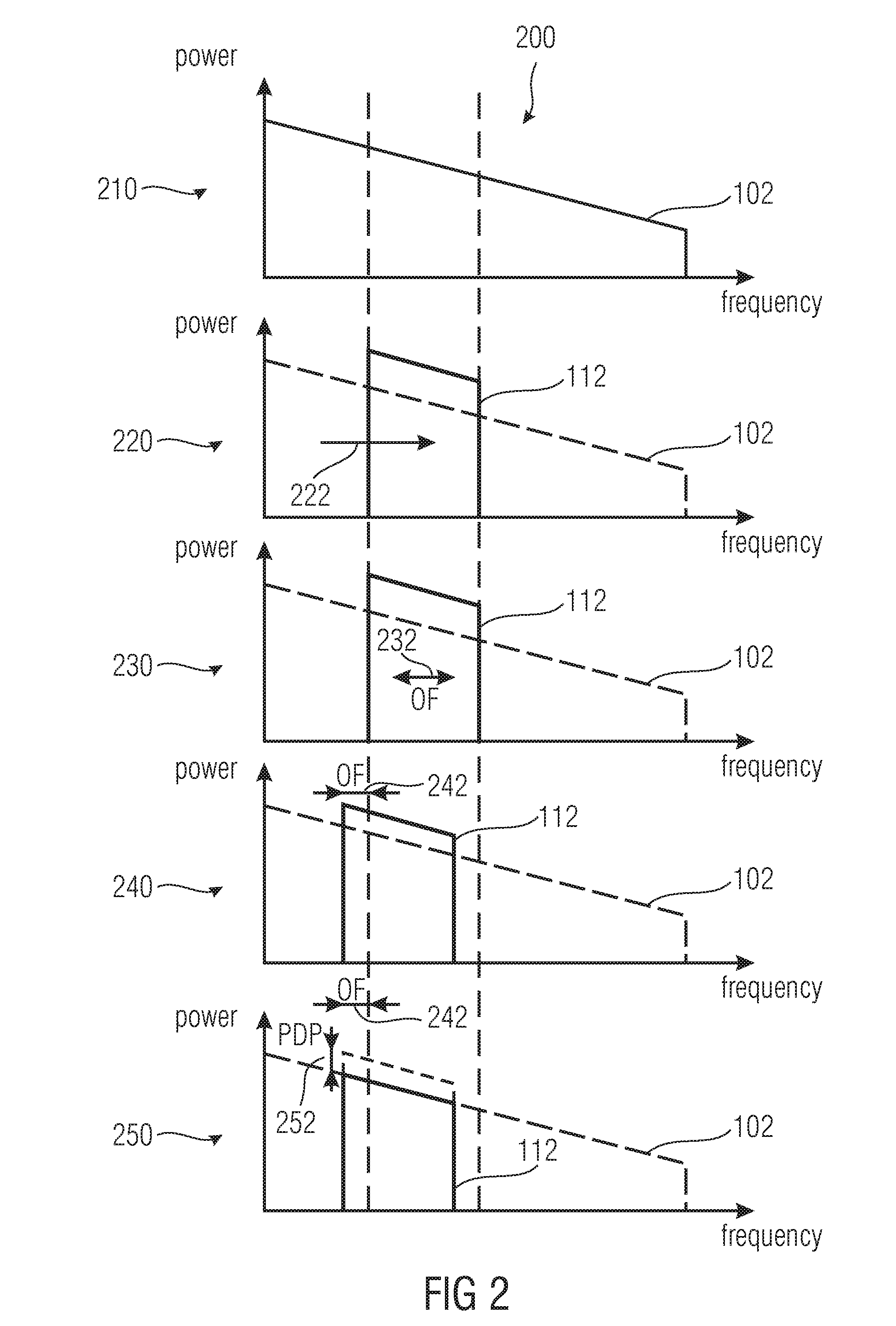
[0042]Embodiments according to the present invention are based on the central idea that a bandwidth extension high-frequency signal which is also called patch, may be generated and compared with the original input audio signal. By using a different offset frequency of the bandwidth extension high-frequency signal or several bandwidth extension high-frequency signals with different offset frequencies, a plurality of comparison parameters corresponding to the different offset frequencies may be calculated. The comparison parameters may be related to a quantity associated with the audio quality. Therefore, a comparison parameter may be determined assuring the compatibility of the bandwidth extension high-frequency signal and the input audio signal, and as a consequence making the audio quality improve.
[0043]The bit rate for transmission or storage of the encoded audio signal may be decreased by using a parameter indication based on the offset frequency corresponding to the determined comparison parameter for a reconstruction of the high-frequency band of the original input audio signal. In this way, only a low frequency portion of the input audio signal and the parameter indication need to be stored or transmitted.
[0047]It is an advantage of embodiments of the invention that an improved coding scheme for audio signals which allow increasing the audio quality and / or decreasing the bit rate for transmission or storage, is provided.

Problems solved by technology

The coding algorithm used for this, in particular when achieving lowest bit rates, leads to the reduction of the audio quality which is often mainly caused by an encoder side limitation of the audio signal bandwidth to be transmitted.
In particular, filterbank calculations and patching in the filterbank domain may become a high computational effort.
Therefore, the complexity of the core coder is increased.
Harmonic bandwidth extension methods often exhibits a high complexity, while methods of complexity-reduced bandwidth extension show quality losses.
In the particular case where a low bit rate is combined with a small bandwidth of the low band, artifacts such as roughness and a timbre perceived as unpleasant may occur.
For example, within SBR, the juxtaposition of the coded components and the replicated components, occurring at the boundary between the low and the high bands, may cause rough sound impressions.
In general, known bandwidth extension methods provide audio signals at a low bit rate, but with poor audio quality or a good audio quality at high bit rates.

Method used


Image

  • Audio encoder and bandwidth extension decoder
  • Audio encoder and bandwidth extension decoder
  • Audio encoder and bandwidth extension decoder

Examples


Embodiment Construction

[0069]In the following, the same reference numerals are partly used for objects and functional units having the same or similar functional properties and the description thereof with regard to a figure shall apply also to other figures in order to reduce redundancy in the description of the embodiments.

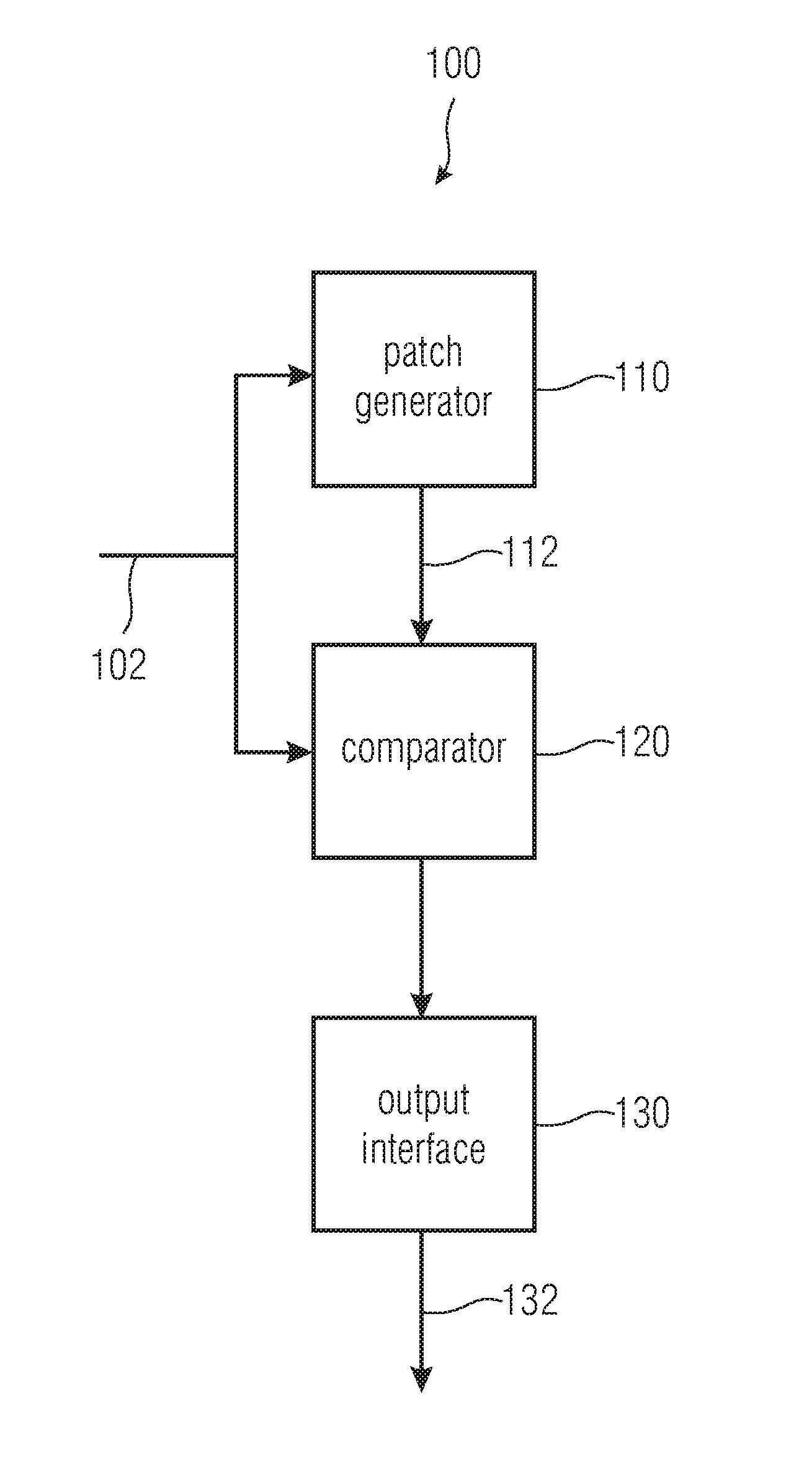
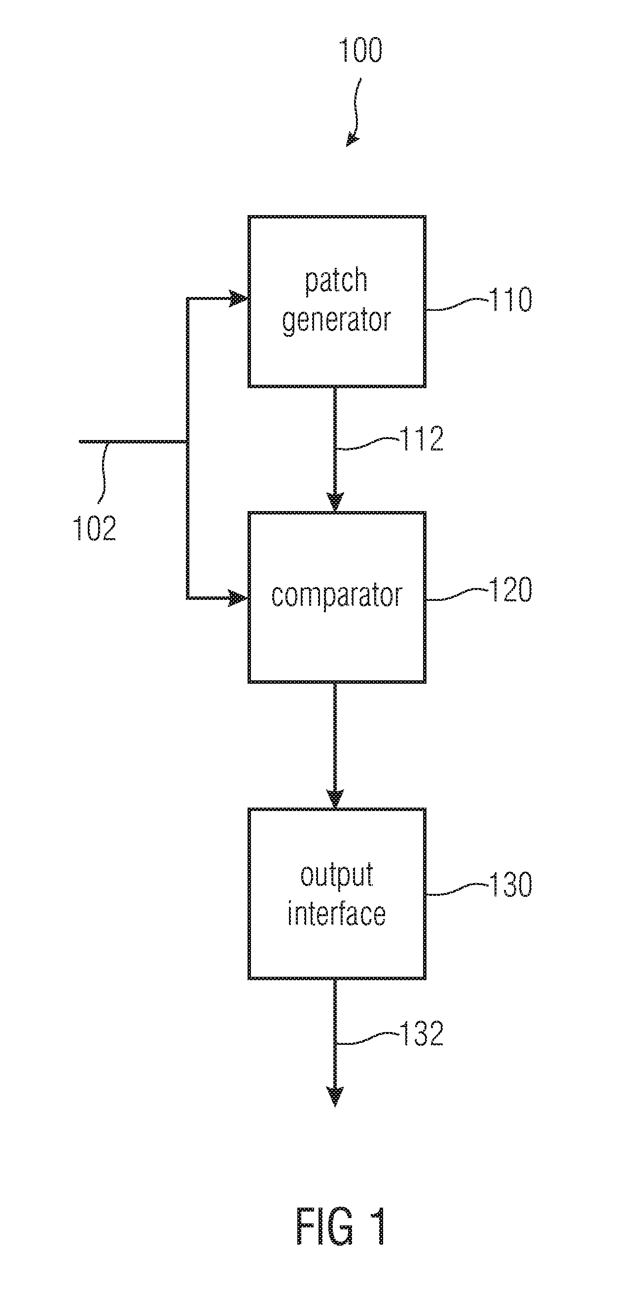
[0070]FIG. 1 shows a block diagram of an audio encoder 100 for providing an output signal 132 according to an embodiment of the invention, using an input audio signal 102. The output signal is suitable for a bandwidth extension at a decoder. Therefore the audio encoder is also called bandwidth extension encoder. The bandwidth extension encoder 100 comprises a patch generator 110, a comparator 120 and an output interface 130. The patch generator 110 is connected to the comparator 120 and the comparator 120 is connected to the output interface 130.

[0071]The patch generator 110 generates at least one bandwidth extension high-frequency signal 112. A bandwidth extension high-frequency sign...


PUM


Abstract

An audio encoder for providing an output signal using an input audio signal includes a patch generator, a comparator and an output interface. The patch generator generates at least one bandwidth extension high-frequency signal, wherein a bandwidth extension high-frequency signal includes a high-frequency band. The high-frequency band of the bandwidth extension high-frequency signal is based on a low frequency band of the input audio signal. A comparator calculates a plurality of comparison parameters. A comparison parameter is calculated based on a comparison of the input audio signal and a generated bandwidth extension high-frequency signal. Each comparison parameter of the plurality of comparison parameters is calculated based on a different offset frequency between the input audio signal and a generated bandwidth extension high-frequency signal. Further, the comparator determines a comparison parameter from the plurality of comparison parameters, wherein the determined comparison parameter fulfils a predefined criterion.

Description

CROSS-REFERENCE TO RELATED APPLICATIONS[0001]This application is a continuation of copending U.S. Application No. 61 / 122,552, filed Dec. 15, 2008, which is incorporated herein by reference in its entirety.[0002]Embodiments according to the invention relate to the audio signal processing and, in particular, an audio encoder, a method for providing an output signal, a bandwidth extension decoder and a method for providing a bandwidth extended audio signal.BACKGROUND OF THE INVENTION[0003]The hearing adapted encoding of audio signals for data reduction for an efficient storage and transmission of these signals has gained acceptance in many fields. Encoding algorithms are known, for instance, as MPEG 1 / 2 LAYER 3 “MP3” or MPEG 4 AAC. The coding algorithm used for this, in particular when achieving lowest bit rates, leads to the reduction of the audio quality which is often mainly caused by an encoder side limitation of the audio signal bandwidth to be transmitted. A low-pass filtered sig...

Claims


Application Information

Patent Timeline
IPC IPC(8): G10L19/00
CPCG10L19/24G10L19/00G10L21/038G10L19/02G10L21/04G10L19/265
Inventor NAGEL, FREDERIKDISCH, SASCHAFUCHS, GUILLAUMEHERRE, JUERGENGRIEBEL, CHRISTIAN
Owner FRAUNHOFER GESELLSCHAFT ZUR FOERDERUNG DER ANGEWANDTEN FORSCHUNG EV
Learn More