
User Interface for Signal Integrity Network Analyzer

a signal integrity network and user interface technology, applied in the direction of transmission monitoring, instruments, line-transmission details, etc., can solve the problems of not offering a number of pre and post measurement functions particularly directed to s-parameter determination and signal analysis, and the operation sequence of vnas is very involved and difficult to perform particular network analysis functions, etc., to achieve the effect of convenient operation for users

Inactive Publication Date: 2011-11-24
TELEDYNE LECROY
View PDF7 Cites 150 Cited by
  • Summary
  • Abstract
  • Description
  • Claims
  • Application Information

AI Technical Summary

Benefits of technology

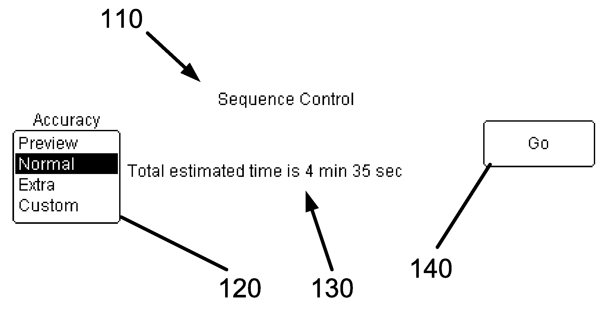
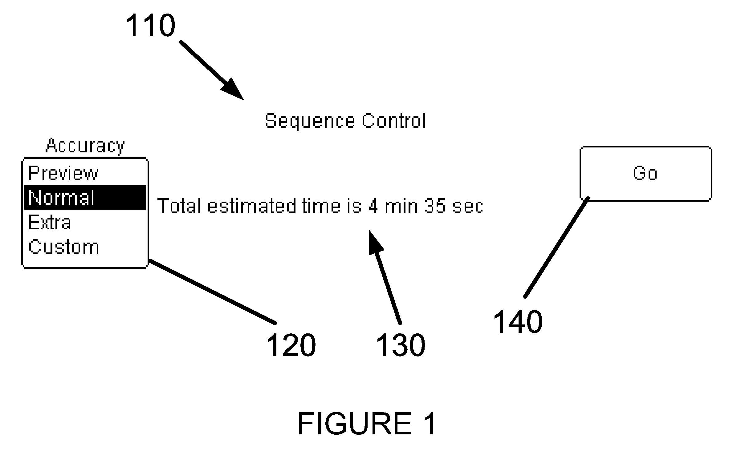
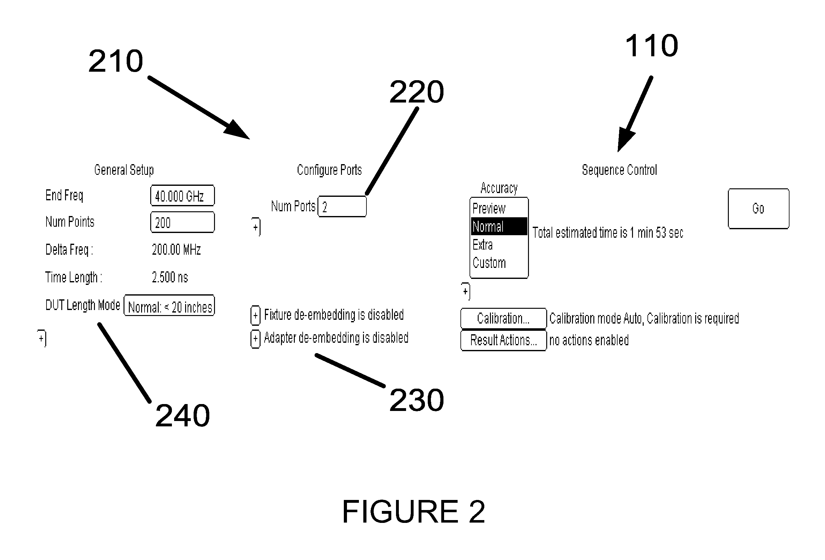
[0013]In accordance with the invention, a test and measurement apparatus comprising a Signal Integrity Network Analyzer (SINA) is provided having a user interface including a plurality of properties making network analyzer functions, such as determining s-parameters for a particular network topology and calibration, easy for a user to perform.
[0014]Therefore, in accordance with the invention, a method and apparatus are provided that provide for a better user experience when analyzing a network topology, and in particular when determining s-parameters for a particular network topology or device under test.

Problems solved by technology

However, VNAs are very expensive and have a very involved and difficult operation sequence to perform particular network analyzation functions, such as determining the s-parameters of a particular network configuration or device under test.
This is primarily because such a VNA is designed to perform a great number of functions, but does not perform these functions according to an easy user interface, and thus fails to offer a number of pre and post measurement functions particularly directed to s-parameter determination and signal analysis.
Because of the manner in which VNAs are built, they tend to be very expensive instruments.
They tend to be so expensive as to be prohibitive in cost to all but those who desperately need one.
The cost increases with the availability of higher frequency performance and an increase in the number of available ports.
The traditional VNA has some features making it more difficult to operate.
This connection and disconnection is time consuming and increases the chances of error.

Method used


Image

  • User Interface for Signal Integrity Network Analyzer
  • User Interface for Signal Integrity Network Analyzer
  • User Interface for Signal Integrity Network Analyzer

Examples


Embodiment Construction

[0038]In traditional s-parameter measurement instrument such as a VNA or the like, and as noted above, calibration of the instrument is required before measurements may be taken with the instrument. Such calibration comprises additional and tedious steps that must be performed before the instrument is able to perform measurements on a Device Under Test (DUT). Such calibration typically requires the sequential physical connection of a number of predetermined loads to the VNA, and then calibrating to these reference values. Such a procedure may comprise sequentially connecting a shorted circuit, a 50 ohm circuit, and an open circuit and reading each with the VNA to provide a reference plane for the device. Once this reference plane is established, then other measurements can be taken by the VNA. Thus, after the reference plane is established, a DUT can then be connected to the VNA to take measurements therefrom. However, even at this point, the user must properly choose numerous setti...


PUM


Abstract

A signal integrity network analyzer is provided. The analyzer preferably includes a characterization module for characterizing a device under test, an acquisition module for acquiring a waveform, a de-embedding module for selectively embedding and de-embedding on or more system fixtures, and an analysis module for performing analysis on the acquired waveform, with one or more system features selectively embedded or de-embedded. A single user interface is provided and is adapted to control the characterization module, the acquisition module, the de-embedding module and the analysis module.

Description

CROSS REFERENCE TO RELATED APPLICATIONS[0001]This application claims the benefit of U.S. Provisional Patent Application Ser. No. 61 / 299,512 “User Interface for Time Domain Network Analyzer”, filed Jan. 29, 2010 to Libby et al., the entire contents thereof being incorporated herein by reference.FIELD OF THE INVENTION[0002]This invention is related generally to a method and apparatus for operation of a Signal Integrity Network Analyzer, and more particularly to features associated with a user interface thereof.BACKGROUND OF THE INVENTION[0003]A TDR (Time Domain Reflectometry) system measures the reflections of an incident waveform from impedance discontinuities in a system under test. Typical TDR systems may include sonar to detect underwater objects, ultrasound to detect objects inside the body and as described in this invention, voltage steps to detect discontinuities in electrical systems. A Signal Integrity Network Analyzer constructed in accordance with various embodiments of the...

Claims


Application Information

Patent Timeline
IPC IPC(8): H04B17/00
CPCG01R1/025G01R13/029G01R35/005G01R27/28G01R27/04
Inventor LIBBY, JONATHANPATEL, HITESHPUPALAIKIS, PETER J.GRAEF, DAVID
Owner TELEDYNE LECROY
Learn More