
Ultrasonic testing method and apparatus

a testing method and ultrasonic technology, applied in the direction of instruments, specific gravity measurement, magnetic property measurement, etc., can solve the problems of boundary portion, deterioration of target flaw detection, so as to facilitate the detection of target flaw and high accuracy

Active Publication Date: 2011-11-24
NIPPON STEEL CORP
View PDF6 Cites 10 Cited by
  • Summary
  • Abstract
  • Description
  • Claims
  • Application Information

AI Technical Summary

Benefits of technology

[0015]The present invention has been made to solve the above problems with the prior art, and accordingly an object thereof is to provide an ultrasonic testing method and apparatus capable of easily setting the proper switching pitch for transducers that is proper for accurately detecting target flaws when a test object is tested by using an ultrasonic probe including a plurality of transducers.
[0022]Also, according to the present invention, in the testing step, the test object is tested with testing sensitivity (amplification degree of echo intensity) adjusted beforehand for each selected m number of transducers so that the highest echo intensities from target flaws received by each selected m number of transducers are approximately equivalent. As described above, the target flaw is located in the range of the effective beam width of any selected m number of transducers in which the testing sensitivity is regulated so that the highest echo intensities are approximately equivalent. Therefore, even if the echo from a target flaw is detected by any selected m number of transducers (in other words, even if a target flaw is present at any location in the testing region of ultrasonic probe), a flaw echo intensity not lower than the predetermined intensity (for example, −3 dB when the maximum value of flaw echo intensity obtained with the ultrasonic probe is set at 0 dB) can be obtained, so that a target flaw can be detected with high accuracy.
[0023]As described above, according to the present invention, by setting the switching pitch length P (mm) of m number of transducers to be selected satisfying formula (1), a target flaw can be detected with high accuracy. That is to say, the conventional trial and error need not be repeated, and the switching pitch length P (mm) satisfying formula (1) has only to be selected, so that a proper switching pitch for transducer can be set easily in detecting a target flaw with high accuracy.
[0029]According to the present invention, the amount of relative displacement in the axial direction of the pipe or tube of the first to third ultrasonic probes per one turn of the pipe or tube is set so as to be not larger than the minimum substantial effective beam width of the substantial effective beam widths in the axial direction of the pipe or tube for a target flaw of the first to third ultrasonic probes. Therefore, even if a target flaw is present in any portion of pipe or tube, for all of the first to third ultrasonic probes, the echo intensity from the target flaw is not lower than the predetermined intensity. As a result, all of axial flaw, circumferential flaw, and lamination can be detected with high accuracy.
[0034]According to the present invention, when a test object is tested by using the ultrasonic probe including the plurality of transducers, a proper switching pitch for transducer can be set easily in detecting a target flaw with high accuracy.

Problems solved by technology

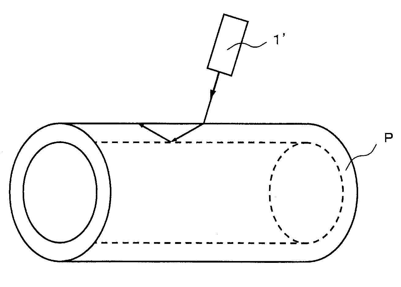
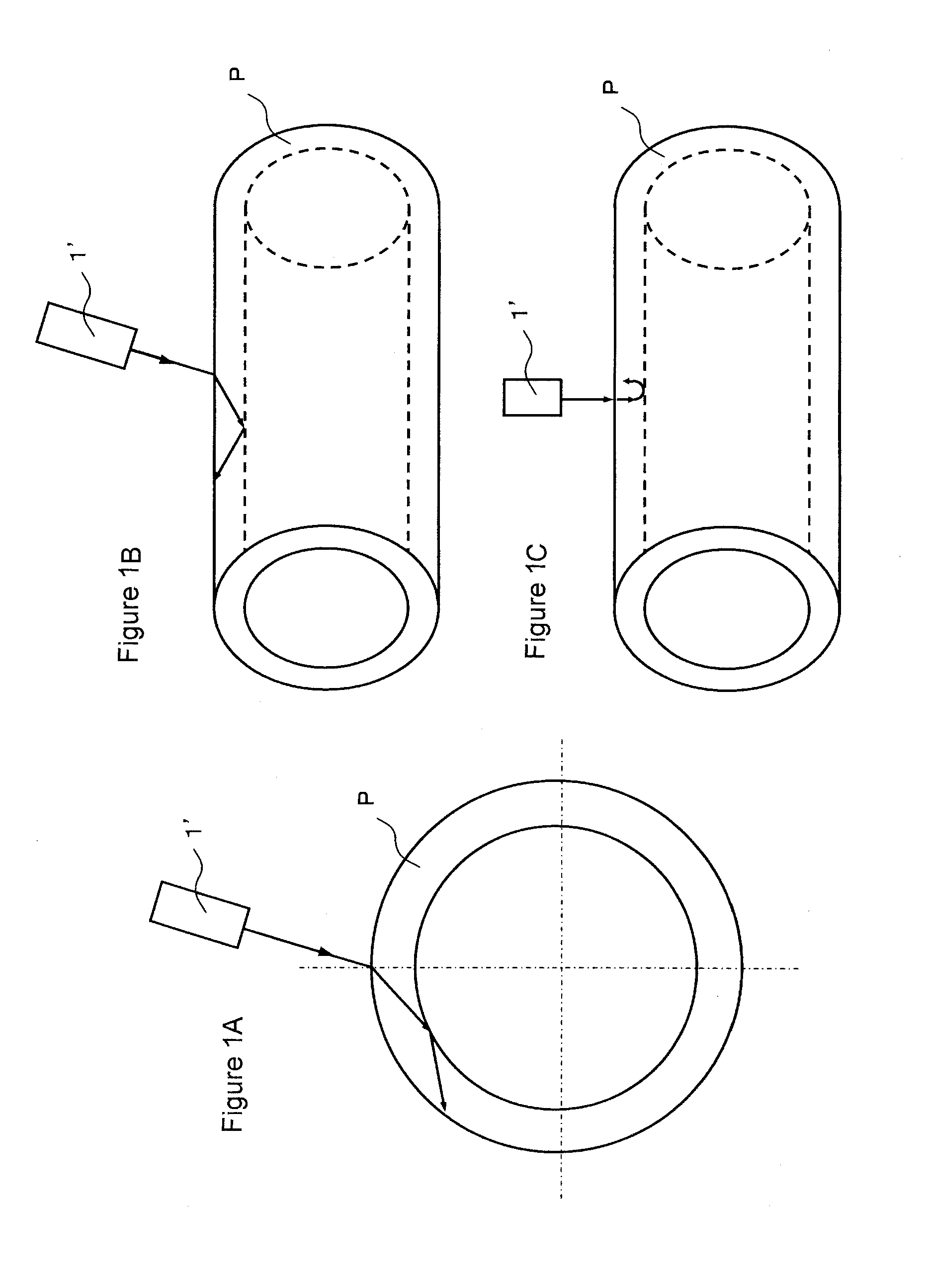
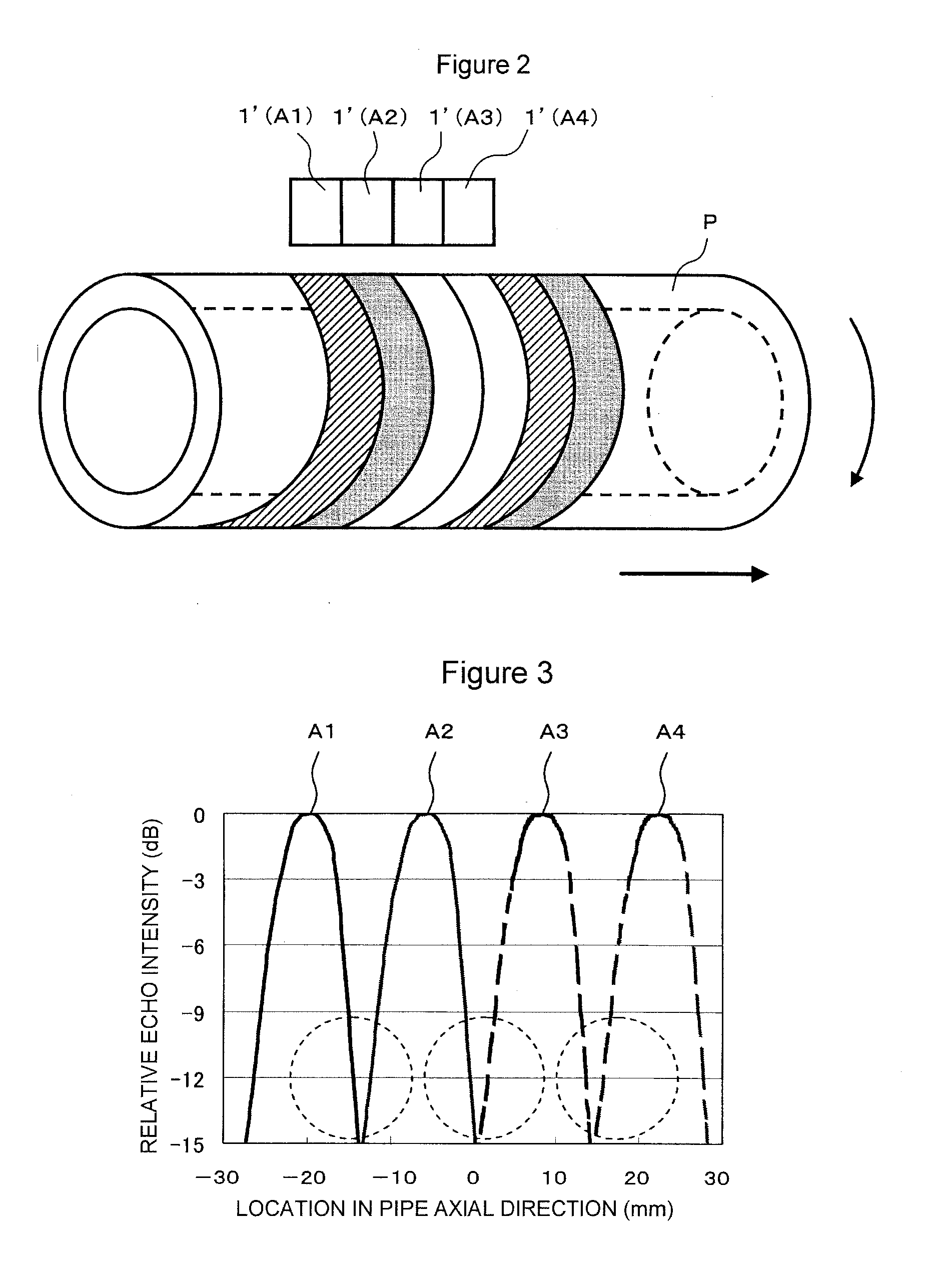
However, the conventional ultrasonic testing method shown in FIG. 2 has a problem that the flaw detectability is deteriorated because of the decrease in sound field intensity at the boundary of sound fields formed by the adjacent ultrasonic probes 1′. FIG. 3 shows a profile example of echo intensity from a circumferential flaw formed on a pipe by machining.
Therefore, it is apparent that the flaw detectability is also markedly deteriorated in this boundary portion.
However, when the technique described in Patent Document 1 is applied to testing of a pipe whose various flaws extend in different directions or have different shapes must be detected, a problem described below arises.
Therefore, with the practical effective beam width derived from the profile of sound field intensity, the switching pitch cannot be determined properly, and the flaw may be overlooked.
Consequently, there arises a problem that the switching pitch must be determined inevitably by repeating trial and error for each type of flaw.

Method used


Image

  • Ultrasonic testing method and apparatus
  • Ultrasonic testing method and apparatus
  • Ultrasonic testing method and apparatus

Examples


first embodiment

[0050]FIG. 5A and 5B give schematic views showing a schematic configuration of an ultrasonic testing apparatus in accordance with a first embodiment of the present invention, FIG. 5A being a front view (a sectional view of the pipe), and FIG. 5B being an enlarged plan view of an ultrasonic probe shown in FIG. 5A (an enlarged plan view in a state in which the ultrasonic probe is not tilted).

[0051]An ultrasonic testing apparatus 100 in accordance with this embodiment is an ultrasonic testing apparatus for detecting circumferential flaws. As shown in FIGS. 5A and 5B, the ultrasonic testing apparatus 100 in accordance with this embodiment comprises an ultrasonic probe 1 including 64 transducers 11 (11-1 to 11-64) arranged along the axial direction of a pipe P, disposed so as to face the pipe P. Also, the ultrasonic testing apparatus 100 in accordance with this embodiment comprises a transmission / reception control device 2 for selecting 30 transducers 11 (in this embodiment, a set of 30 ...

second embodiment

[0073]FIGS. 8A to 8C give schematic views showing a schematic configuration of an ultrasonic testing apparatus in accordance with a second embodiment of the present invention, FIG. 8A being a front view, FIG. 8B being a plan view, and FIG. 8C being an enlarged plan view of an ultrasonic probe (an enlarged plan view in a state in which the ultrasonic probe is not tilted).

[0074]An ultrasonic testing apparatus 100A in accordance with this embodiment is an ultrasonic testing apparatus for detecting flaws present in welded portions. As shown in FIG. 8, the ultrasonic testing apparatus 100A in accordance with this embodiment comprises ultrasonic probes 1A and 1B including 16 transducers 11 (11-1 to 11-16) arranged along the direction perpendicular to the weld line of a welded portion P1 of a pipe P, disposed so as to face the welded portion P1. Also, the ultrasonic testing apparatus 100A in accordance with this embodiment comprises a transmission / reception control device 2 (not shown) for...

third embodiment

[0091]FIG. 11A and 11B give schematic views showing a schematic configuration of an ultrasonic testing apparatus in accordance with a first embodiment of the present invention, FIG. 11A being a front view (a sectional view of the pipe), and FIG. 11B being an enlarged plan view of an ultrasonic probe shown in FIG. 11A (an enlarged plan view in a state in which the ultrasonic probe is not tilted).

[0092]An ultrasonic testing apparatus 100B in accordance with this embodiment is an ultrasonic testing apparatus for detecting a lamination. As shown in FIGS. 11A and 11B, the ultrasonic testing apparatus 100B in accordance with this embodiment comprises an ultrasonic probe 1C including 64 transducers 11 (11-1 to 11-64) arranged along the axial direction of a pipe P, disposed so as to face the pipe P. Also, the ultrasonic testing apparatus 100B in accordance with this embodiment comprises a transmission / reception control device 2 (not shown) for selecting 36 transducers 11 (in this embodiment...


PUM

PropertyMeasurementUnit
ultrasonic testingaaaaaaaaaa
widthaaaaaaaaaa
ultrasonic testing methodaaaaaaaaaa

Abstract

An ultrasonic testing apparatus 100 comprises an ultrasonic probe 1 including n (n≧2) number of transducers arranged along a predetermined direction, disposed so as to face a test object P, and a transmission / reception control device 2 for selecting m (n>m≧1) number of transducers from among the n number of transducers, transmitting ultrasonic waves from the selected m number of transducers toward the test object, receiving the ultrasonic waves therefrom, and switched m number of transducers to b selected successively. If an angle that the arrangement direction of the transducers makes with the surface of the test object which ultrasonic waves enter is θ, and the effective beam width of each selected m number of transducers with respect to a target flaw is W1, the transmission / reception control device switches m number of transducers to be selected successively by a switching pitch length P satisfying the formula: P≦W1·cosθ.

Description

TECHNICAL FIELD[0001]The present invention relates to an ultrasonic testing method and apparatus capable of accurately detecting various flaws present in test objects such as pipe or tube. More particularly, it relates to an ultrasonic testing method and apparatus capable of easily setting the proper switching pitch for transducers for accurately detecting target flaws when a test object is tested by using an ultrasonic probe including a plurality of transducers.BACKGROUND ART[0002]In ultrasonic testing of pipe or tube (Hereinafter, “pipe or tube” is referred to as a pipe when deemed appropriate.), it is necessary to detect not only an axial flaw (a flaw extending in the axial direction of pipe) but also a circumferential flaw (a flaw extending in the circumferential direction of pipe) and a planar flaw parallel with the inner and outer surfaces of pipe called a lamination.[0003]The axial flaw is detected by transmitting and receiving ultrasonic waves by using an ultrasonic probe 1′...

Claims


Application Information

Patent Timeline
Patent Type & Authority Applications(United States)
IPC IPC(8): G01N29/00
CPCG01N29/043G01N2291/2634G01N2291/106G01N29/262
Inventor YAMANO, MASAKIIKEDA, MASAMIFUJIWARA, KENJIKUBOTA, HIROSHI
Owner NIPPON STEEL CORP
Learn More