Capacitive dc-dc converter

a capacitive converter and dc-dc technology, applied in the direction of dc-dc conversion, power conversion systems, instruments, etc., can solve the problems of linear regulators then inefficient, capacitive converters always less than 100% efficient, and it is difficult to miniaturize inductors

Inactive Publication Date: 2011-11-17
NXP BV
View PDF6 Cites 9 Cited by
  • Summary
  • Abstract
  • Description
  • Claims
  • Application Information

AI Technical Summary

Benefits of technology

[0011]It is an object of the present invention to provide an improved capacitive converter, which allows for a high-efficiency voltage conversion, and overweight of the need for a linear regulator.

Problems solved by technology

Thus although able to accommodate widely separated supply and load voltages, a linear regulator is then inefficient.
Although in theory and ignoring resistive and switch losses, an inductive converter could be 100% efficient, a capacitive converter will always be less than 100% efficient, due to the ripple losses resulting from the energy ½CΔV2 lost each time the capacitor is charged over an excursion ΔV
However, in practice it is hard to miniaturize inductors and keeping the Q factor at an acceptable level.
Alternatively, it has the proposed that the switching frequency be changed; however, this can result in unpredictable magnetic interference with communication lines.
A change of the duty cycle prevents frequency changes, but might result in decreased efficiency and strongly enhanced higher harmonics.
Thus these techniques are unsatisfactory in that they are associated with an increased risk of electromagnetic interference (emi).
To date, there has been no satisfactory solution, which effectively combines the advantages of capacitive converters with continuously variable control of the ratio between the input and output, or supply and load, voltages.

Method used


Image

  • Capacitive dc-dc converter
  • Capacitive dc-dc converter
  • Capacitive dc-dc converter

Examples


first embodiment

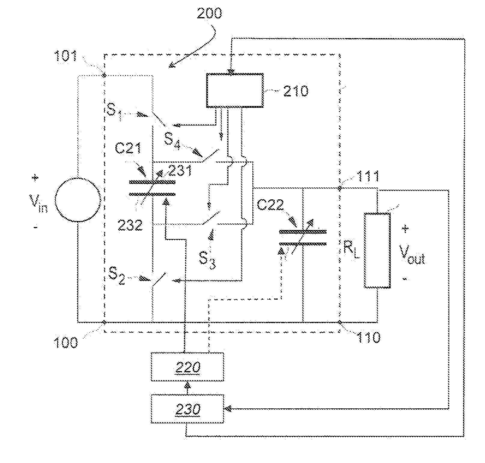
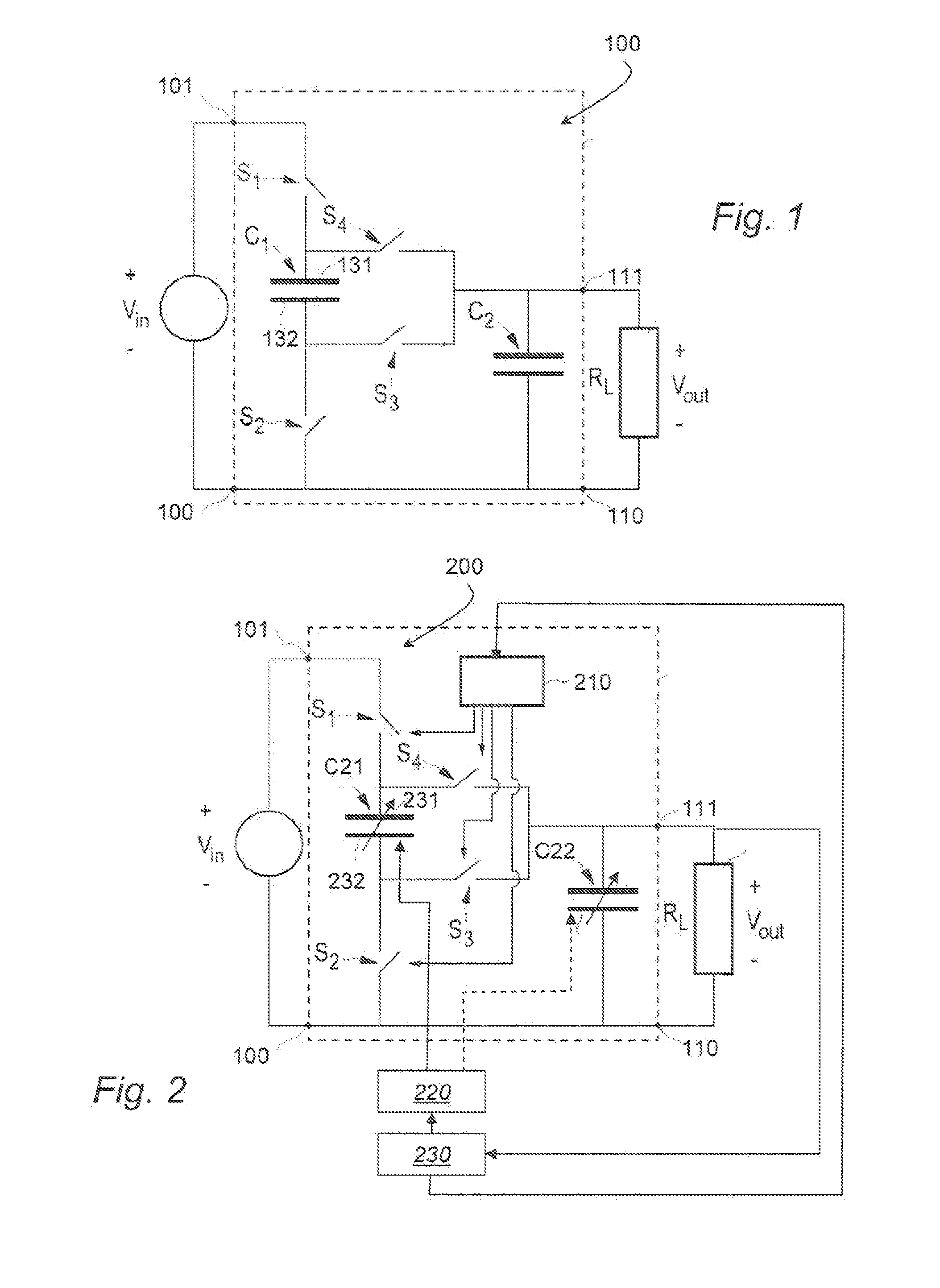
[0041]FIG. 2 shows the DC-DC capacitive converter according to the invention. The converter is similar to that depicted in FIG. 1, and corresponding components are thus referenced by corresponding reference numerals. In this converter, however, the charge-pump capacitor C1 is replaced by a variable charge-pump capacitor C21, having top and bottom electrodes to 231 and 232 respectively. Similarly, capacitor C2 is replaced by the variable capacitor C22. The control unit for controlling switches S1 through S4 is shown at 210; its operation is similar to that described above with reference to FIG. 1. However, the control unit 210 differs from that described with reference to FIG. 1, in that it is also responsive to the output from a control loop 230. The control loop is responsive to the output +Vout, and in particular to the high side 111 of the output, and thus control loop 230 is shown in FIG. 2 as having an input connected to +Vout. In addition to controlling the control unit 210, c...

second embodiment

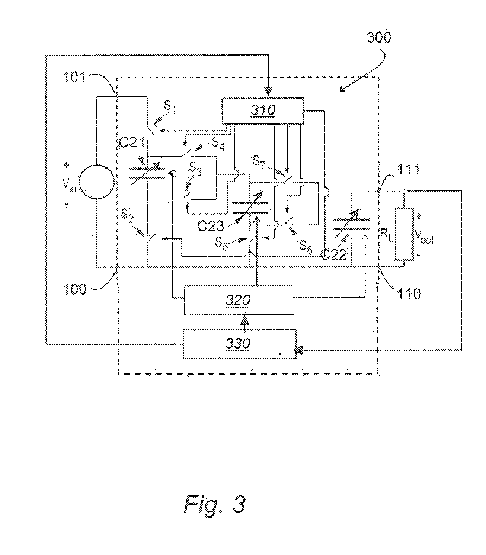
[0044]the invention is illustrated in the schematic circuit diagram of FIG. 3. The layout of this embodiment is generically similar to that described above with reference to FIG. 2; however this embodiment differs from that shown in FIG. 2, in that this embodiment includes a further charge-pump capacitor C23. As a consequence, there are more control switches, and the bias circuit or bias control 320 controls two or three capacitors rather than one or two as in the previous embodiment.

[0045]The arrangement of the control switches differs in detail from that in the previous embodiments, in that, instead of connecting the high side 111 of the output to the first and second electrode of capacitor C1 respectively, switches S4 and S3 connect the respective electrode to the first electrode of further charge-pump variable capacitor C23. The second electrode of the further charge-pump variable capacitor C23 is connected to the common low sides 100 and 110 of input and output by via switch S5...


PUM


Abstract

A charge-pump capacitive DC-DC converter (200) is disclosed, which includes a reconfigurable charge-pump capacitor array. The DC-DC converter is configured to provide a continuously variable ratio between its input voltage (Vin) and its output voltage (Vout), by means of at least one of the at least one charge-pump capacitors (C21, C22) forming the reconfigurable array being a variable capacitor. In the embodiments, the one or more variable capacitors (C21, C22) may be a ferroelectric capacitor, an anti-ferroelectric capacitor, or other ferrioc capacitor. The DC-DC converter (200) may provide a bias circuit to the capacitor or capacitors, and may further provide a control loop (220, 230). Alternatively, the capacitor may provide a degree of self-control.

Description

FIELD OF THE INVENTION[0001]This invention relates to DC-DC converters. It is particularly concerned with charge-pump capacitive DC-DC converters, and methods of controlling such DC-DC converters.BACKGROUND OF THE INVENTION[0002]A simple method of supplying a load with a voltage which is lower than the available supply voltage is by means of a linear regulator. A linear regulator basically is a controlled resistance in series with the load. However, as the load voltage decreases relative to the supply voltage, the voltage required to be dropped across the controlled resistance increases. The power dissipated in the controlled resistance increases, and the overall efficiency of the regulator decreases. Thus although able to accommodate widely separated supply and load voltages, a linear regulator is then inefficient.[0003]An alternative solution, which is being used increasingly, is the switched-mode power supply or DC-DC converter. Instead of a resistive component, a reactive compon...

Claims


Application Information

Patent Timeline
Patent Type & Authority Applications(United States)
IPC IPC(8): H02M3/06
CPCH02M3/07
Inventor REIMANN, KLAUSBESLING, WILLEM FREDERIK ADRIANUSBERGVELD, HENDRIK JOHANNESNOVOSELOV, PAVEL
Owner NXP BV
Why Eureka
Try Eureka