LED light emitting device

a light-emitting device and led light technology, which is applied in the direction of solid-state devices, electric lighting sources, electric light sources, etc., can solve the problems of difficult control, difficult control, and difficulty in recognizing white light as easy to gain, and achieve fine control of color temperature. , the effect of recognizing white ligh

Inactive Publication Date: 2011-11-17
CCS INC
View PDF10 Cites 21 Cited by
  • Summary
  • Abstract
  • Description
  • Claims
  • Application Information

AI Technical Summary

Benefits of technology

[0022]According to the present invention having such configurations, even as viewed from an extremely close distance, recognition as white light is easily gained; also fine control of a color temperature is easily performed; and further, with ensuring predetermined lightness or higher, a fine adjustment of the color temperature of the white light can be made near the black body locus.

Problems solved by technology

However, the respective LED elements have different forward voltage drops (vf), i.e., the red LED element has a forward voltage drop of approximately 2.0 V, green LED element approximately 3.3 V, and blue LED element approximately 3.4 V, so that, to adjust amounts of currents applied to the respective LED elements to adjust a balance among light amounts, a complicated calculation process is required, and for this reason, there is a problem that controlling a color temperature of the white light is difficult.
For this reason, in order to use such a conventional LED light emitting device as a white light source, a sufficient distance is required from the light source, and therefore the conventional LED light emitting device is inappropriate for a light source for irradiating a close place.
Such a problem is also recognized even in an LED light emitting device that separately uses red, green, and blue phosphors without combining them to form, in the same device, a red color light emitting part, a green color light emitting part, and a blue color light emitting part that are partitioned from one another.
For this reason, a lot-based variation or difference in deterioration rate among LED elements largely affects the color temperature of the resultant white light, and therefore it is not easy to control it, for example, an extremely fine adjustment or complicated calculation process is required.
This means that in an LED light emitting device employing a configuration in which red light, green light, and blue light, which were once emitted outside the device, are mixed to generate white light, even in the case of attempting to finely adjust a color temperature of the white light, the color temperature is likely to be largely changed, and in such a type of LED light emitting device, controlling a color temperature of white light requires a complicated calculation process after all, and is not easy.

Method used


Image

  • LED light emitting device
  • LED light emitting device
  • LED light emitting device

Examples


first embodiment

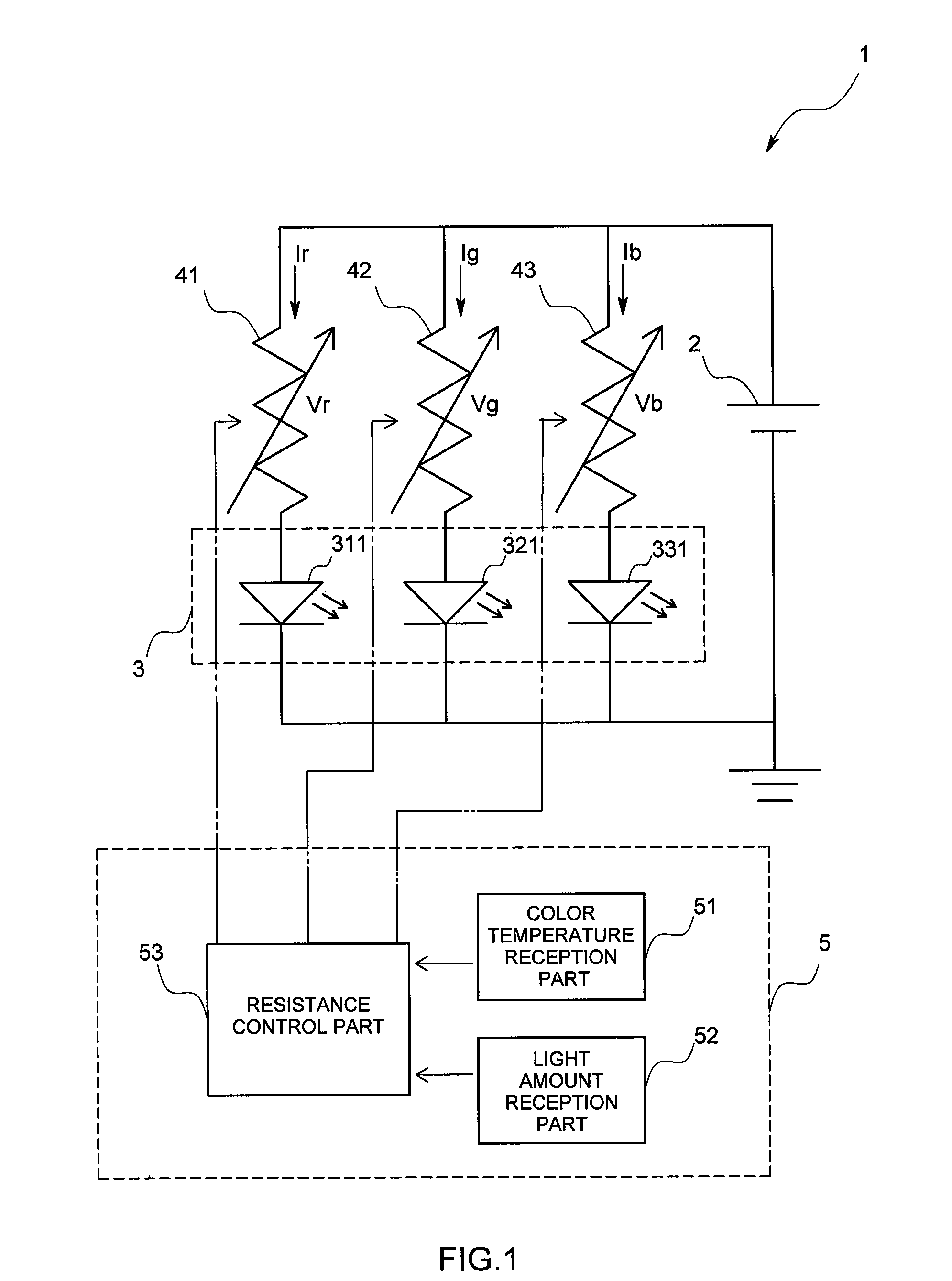
[0037]A light emitting system 1 according to the present embodiment is, as illustrated in FIGS. 1 and 2, provided with: a power source 2; an LED light emitting device 3 having three types of light emitting parts 31, 32, and 33 that are provided with LED elements 311, 321, 331 to emit red light, green light, and blue light, respectively; variable resistors 41, 42, and 42 that are connected to the LED elements 311, 321, and 331 of the light emitting parts 31, 32, and 33, respectively; and a control device 5.

[0038]In the following, the respective parts are described in detail.

[0039]The power source 2 supplies a voltage larger than voltage drops of the LED elements 311, 321, and 331.

[0040]The LED light emitting device 3 is provided with the red color based light emitting part 31 that emits the red light, green color based light emitting part 32 that emits the green light, and blue color based light emitting part 33 that emits the blue light, and each of the light emitting parts 31, 32, ...

second embodiment

[0064]In the following, a second embodiment is described referring to FIGS. 8 and 9; however, in the following description, the description is provided with focusing on different points from the first embodiment.

[0065]An LED light emitting device 3 in the second embodiment is provided with: a red color based light emitting part 31 that contains red phosphors, green phosphors, and blue phosphors at a weight ratio of 70 / 15 / 15 and dominantly emits red light; and a blue color based light emitting part 33 that contains red phosphors, green phosphors, and blue phosphors at a weight ratio of 30 / 25 / 45 and dominantly emits blue light, and as illustrated in FIG. 9, the red color based light emitting part 31 and the blue color based light emitting part 33 overlap with each other in their parts. Also, in an overlapping portion, the red color based light emitting part 31 is positioned below the blue color based light emitting part 33.

[0066]According to the present embodiment, in the part where t...

third embodiment

[0067]In the following, a third embodiment is described referring to FIGS. 10 and 11; however, in the following description, the description is provided with focusing on different points from the first embodiment.

[0068]An LED light emitting device 3 in the third embodiment is provided with: a red color based light emitting part 31 that contains red phosphors, green phosphors, and blue phosphors at a weight ratio of 70 / 15 / 15 and dominantly emits red light; a green color based light emitting part 32 that contains red phosphors, green phosphors, and blue phosphors at a weight ratio of 30 / 40 / 30 and dominantly emits green light; and a blue color based light emitting part 33 that contains red phosphors, green phosphors, and blue phosphors at a weight ratio of 30 / 25 / 45 and dominantly emits blue light, and as illustrated in FIG. 11, the red color based light emitting part 31, green color based light emitting part 32, and blue color based light emitting part 33 overlap with one another in th...


PUM


Abstract

In order to provide an LED light emitting device that can easily control a color temperature of white light, the LED light emitting device is provided with a plurality of types of light emitting parts that: respectively have LED elements that emit ultraviolet radiation or violet color visible light, and phosphors that absorb the ultraviolet radiation or violet color visible light to emit colored light; and emit the colored light, wherein: the colored light emitted by the plurality of types of light emitting parts become white light when all mixed with each other; the LED elements of the plurality of types of light emitting parts are all the same ones, and mounted on a single base material; and two or more light emitting parts overlap with each other in their parts.

Description

TECHNICAL FIELD[0001]The present invention relates to an LED light emitting device that can easily control a color temperature of white light.BACKGROUND ART[0002]Conventionally, there is known an LED light emitting device that uses three types of LED elements, i.e., red, green, and blue LED elements, to emit white light (Patent literature 1). However, the respective LED elements have different forward voltage drops (vf), i.e., the red LED element has a forward voltage drop of approximately 2.0 V, green LED element approximately 3.3 V, and blue LED element approximately 3.4 V, so that, to adjust amounts of currents applied to the respective LED elements to adjust a balance among light amounts, a complicated calculation process is required, and for this reason, there is a problem that controlling a color temperature of the white light is difficult.[0003]Also, in such a conventional LED light emitting device, red light, green light, and blue light respectively emitted from the LED ligh...

Claims


Application Information

Patent Timeline
IPC IPC(8): H01L31/0216H05B44/00
CPCH01L25/0753H01L33/504H01L33/508H05B33/0821H01L2224/49107H05B33/0857H01L2224/48091H01L2924/00014H05B45/40H05B45/20
Inventor SUZUKI, HIROKAZUKONISHI, JUNTANAKA, YUICHIROYONEDA, KENJI
Owner CCS INC
Why Eureka
Try Eureka