Weather strip and production method for the same

a technology of weather strip and production method, which is applied in the field of weather strip, can solve the problems of increasing the repulsion force (reactive force against the door) of the sealing part, the difficulty of uniformly forming a thin and wide solid layer made from solid rubber on the superficial part by extruding, and the technology is not yet satisfactory, so as to reduce the probability of inviting, reduce the effect of work efficiency and preventing the probability of inviting

Inactive Publication Date: 2011-11-17
TOYODA GOSEI CO LTD +1
View PDF10 Cites 1 Cited by
  • Summary
  • Abstract
  • Description
  • Claims
  • Application Information

AI Technical Summary

Benefits of technology

[0011]This invention has been accomplished in order to solve the above-described problems, and an object thereof is to provide a weather strip capable of enhancing durability of a sealing part as well as of suppressing the troubles caused by the too large reactive force.

Problems solved by technology

However, it is in fact difficult to uniformly form a thin and wide solid layer made from a solid rubber on the superficial part by extruding.
Accordingly, there is a fear that the solid layer is increased in thickness leading to an increase in thickness of the sealing part to result in undesirably large increase in repulsion force (reactive force against the door) of the sealing part.
Though it is possible to achieve the solid layer thinner than that obtained by the simultaneous formation of the solid layer by employing the technology disclosed in JP-A-10-52867, the technology is not yet satisfactory since there is a fear for inviting the increase in reactive force in the case of the above-described sealing part.
Further, with the technology disclosed in JP-A-10-52867, there is a fear that, even when only the sealing part is irradiated with the electron beam with a region (trim part, etc.) except for the sealing part is being masked, the masked part such as a peripheral portion of the sealing part, for example, can be crosslinked in addition to the sealing part.
More specifically, since it is difficult to properly define the part to be hardened by the electron beam irradiation, there is a fear that the parts that do not require the increase in rigidity can be increased in rigidity.
Also, since an apparatus for the electron beam irradiation is required, an equipment cost can be remarkably increased.

Method used


Image

  • Weather strip and production method for the same
  • Weather strip and production method for the same
  • Weather strip and production method for the same

Examples


Embodiment Construction

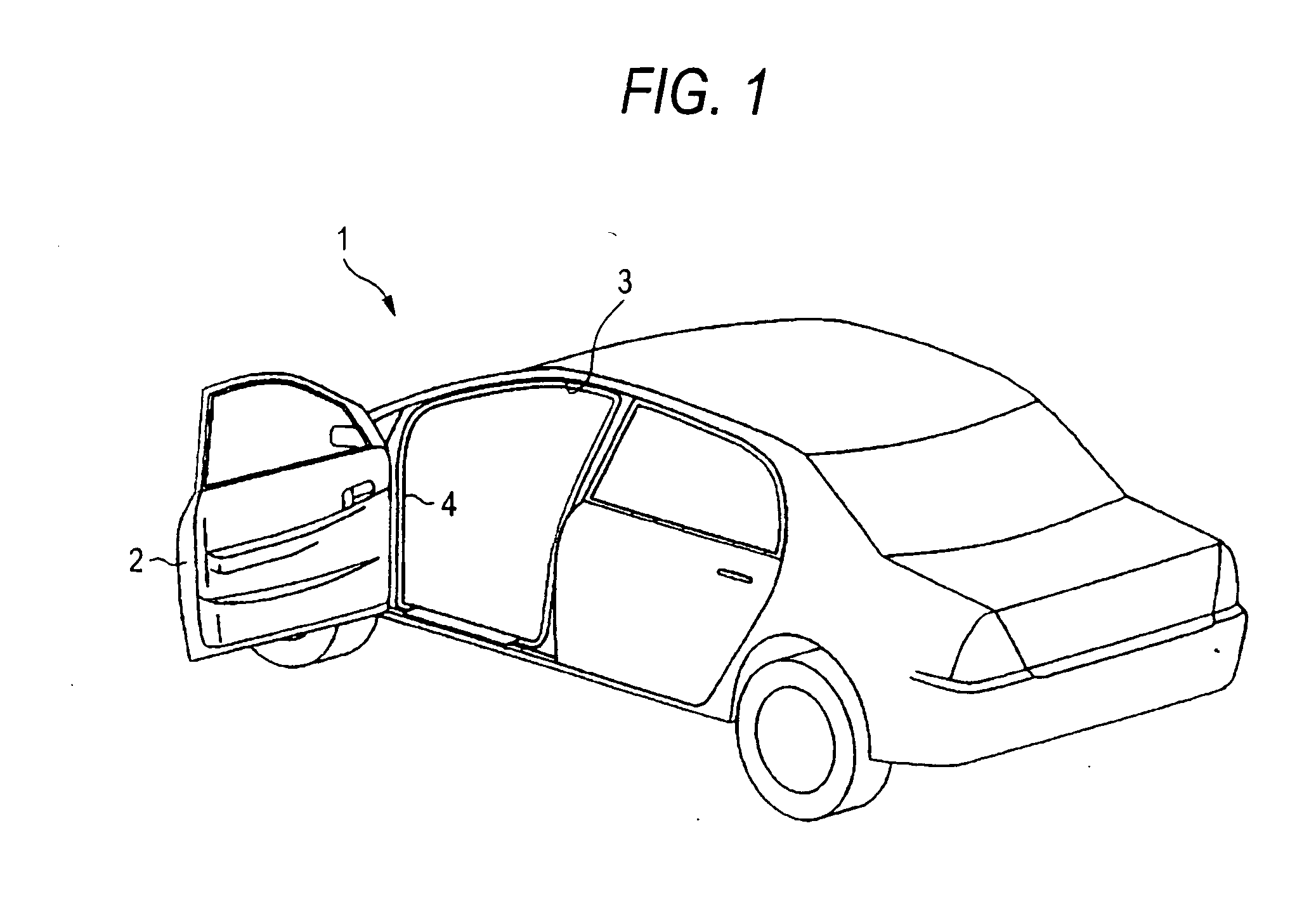
[0044]Hereinafter, one embodiment will be described with reference to drawings. As shown in FIG. 1, an automobile 1 as a vehicle is provided with a vehicle door (front door in FIG. 1, and hereinafter simply referred to as door 2) which is capable of opening and closing, and a weather strip 4 is attached to a peripheral part of a door opening 3 of a vehicle body (vehicle main body) corresponding to the door 2. The weather strip 4 of this embodiment is molded by an extruding method and has a substantially ring-like shape as a whole. In other words, substantially whole part of the weather strip 4 forms an extruded part.

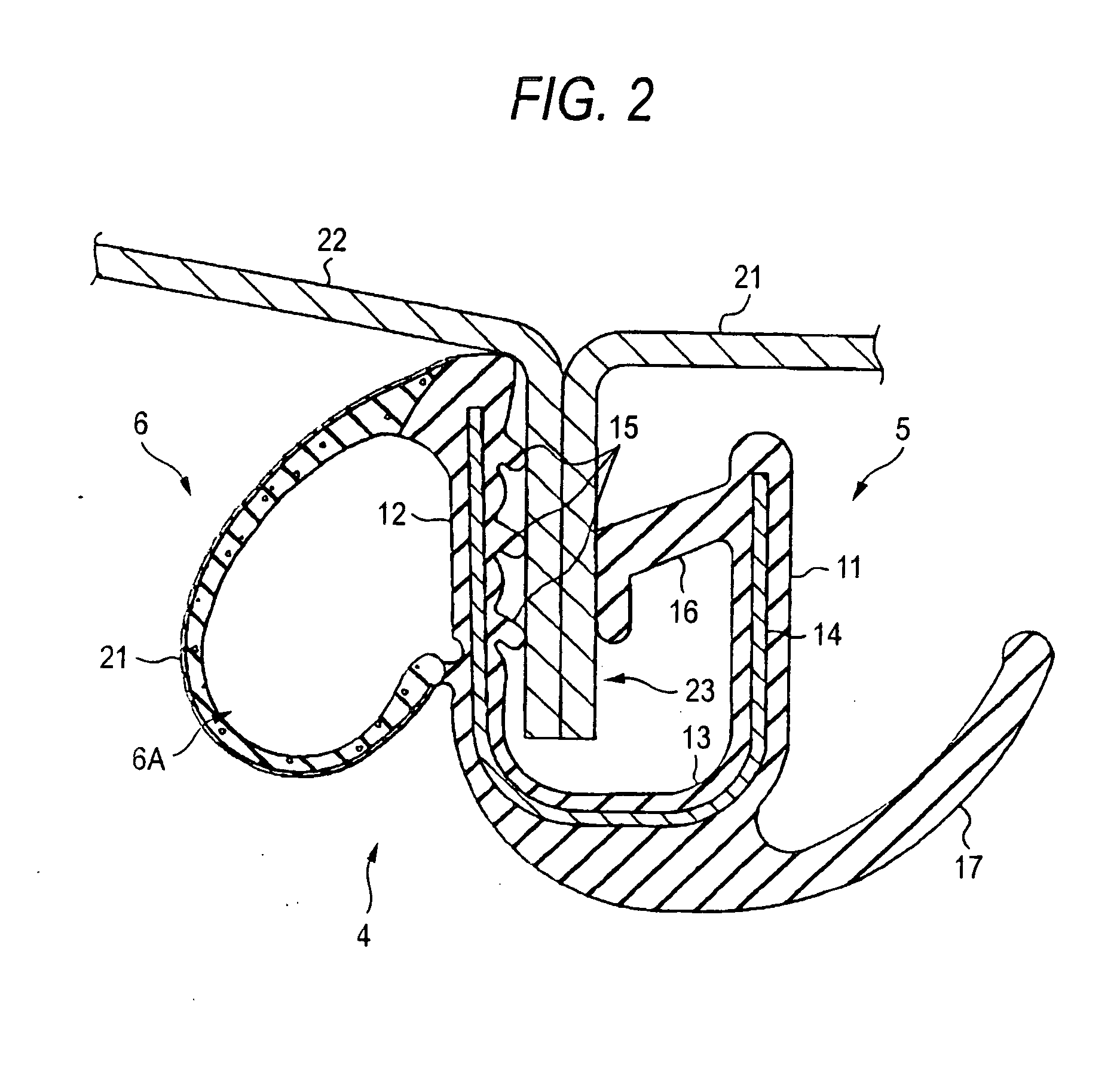
[0045]As shown in FIG. 2, the weather strip 4 is provided with a trim part 5 and a sealing part 6. The trim part 5 is provided with a connection part 13 for connecting a vehicle interior side wall 11, a vehicle exterior side wall 12, and both of the walls 11 and 12 and has a substantially U-shaped sectional shape as a whole. The trim part 5 is formed from a solid EPDM (e...


PUM

PropertyMeasurementUnit
thicknessaaaaaaaaaa
widthaaaaaaaaaa
thicknessaaaaaaaaaa

Abstract

A method for producing a weather strip, includes an extrusion step for extruding a non-vulcanized and non-foamed rubber into a predetermined shape, a coating step for coating a treatment liquid containing a simple sulfur, a sulfur compound, or both of the simple sulfur and the sulfur compound on an outer surface of a sealing part of a non-vulcanized and non-foamed intermediate molded body that is molded by the extrusion step, and a vulcanizing and foaming step for forming a skin layer in a non-foamed state by heating and vulcanizing a surface of the treatment liquid, and forming a sponge layer by vulcanizing and foaming the non-vulcanized and non-foamed rubber that is internal from the skin layer by passing the intermediate molded body on which the treatment liquid has been coated during the coating step through a heating zone, the steps being performed when molding the extruded part.

Description

RELATED APPLICATIONS[0001]The present application is a Divisional application of U.S. patent application Ser. No. 11 / 892,165 which was filed on Aug. 20, 2007.BACKGROUND OF THE INVENTION[0002]1. Field of the Invention[0003]This invention relates to a weather strip to be attached to a peripheral part of a door opening of a vehicle and the like as well as to a method for producing the same.[0004]2. Related Art[0005]In general, a weather strip is provided on a peripheral part of a door opening and a peripheral part of a door of a vehicle such as an automobile. The weather strip is provided with an attachment base (a trim part having a section in a substantially U-shape, for example) to be attached to an attachment part (flange, for example) provided on the vehicle door opening peripheral part and the vehicle door opening peripheral part and a sealing part provided as being projected from the attachment base and having a hollow part. When the door is closed, the sealing part is brought i...

Claims


Application Information

Patent Timeline
Patent Type & Authority Applications(United States)
IPC IPC(8): B60J10/08B29C53/00B60R13/06
CPCB29C47/0023B60J10/0068B29L2031/26B29C47/026Y10T29/49982B60J10/08B29C47/065B29C47/0052B60J10/0008B60J10/0005B60J10/16B60J10/17B60J10/33B60J10/80B29C48/0016B29C48/09B29C48/155B29C48/21
Inventor HOTTA, MASATOSHIWATANABE, TAMOTSU
Owner TOYODA GOSEI CO LTD
Why Eureka
Try Eureka