
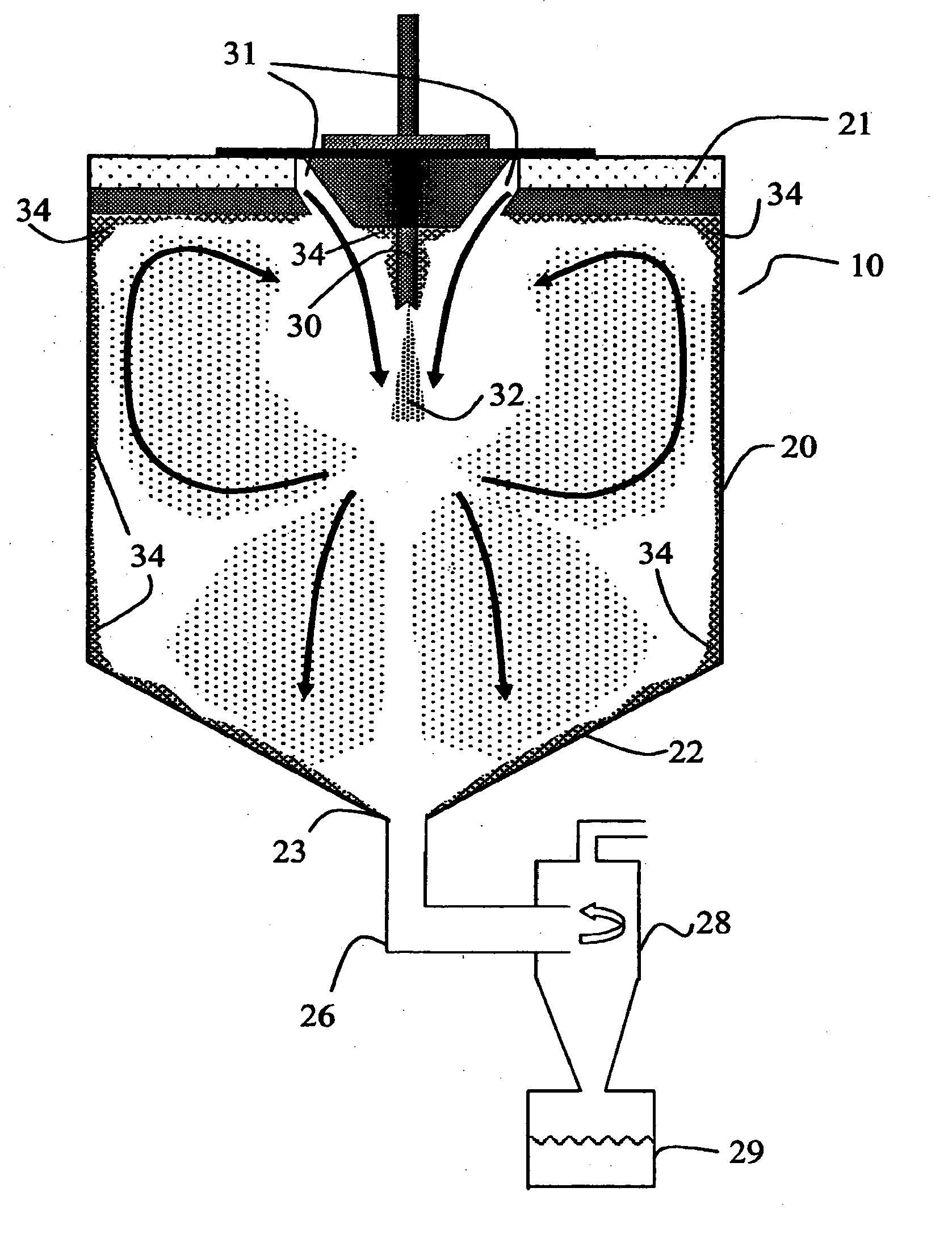
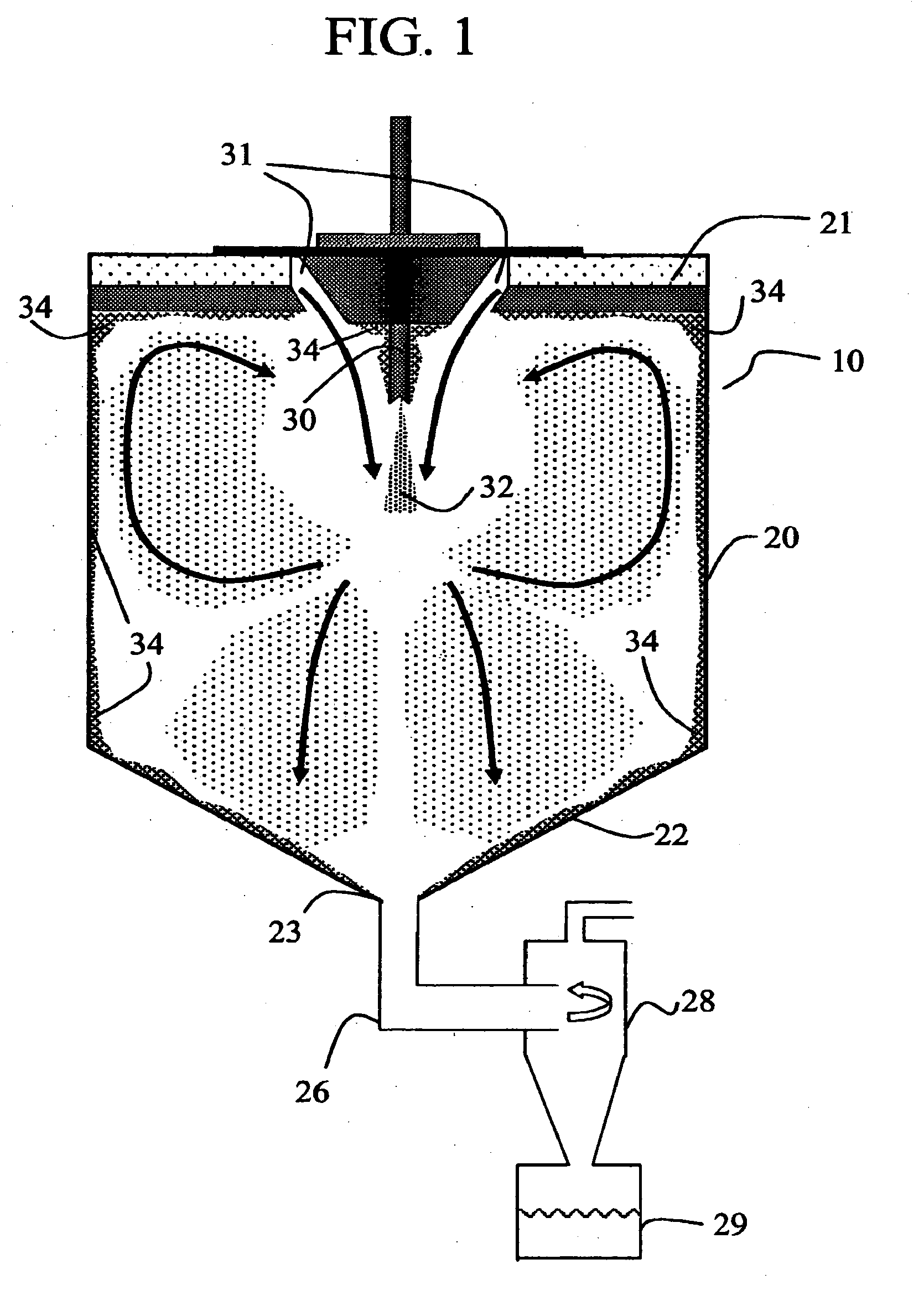
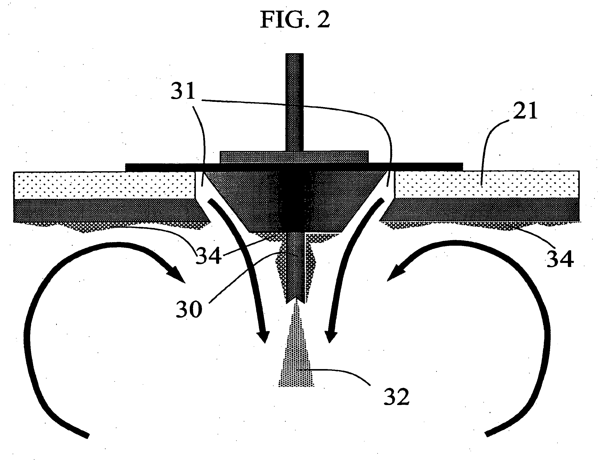
Method for making homogeneous spray-dried solid amorphous drug dispersions utilizing modified spray-drying apparatus

a technology of spray-drying apparatus and dispersions, which is applied in the direction of lighting and heating apparatus, pharmaceutical product form changes, furniture, etc., can solve the problems of poor collection efficiency, poor flow characteristics of dispersions produced using spray-drying apparatus equipped with two-fluid nozzles, etc., and achieve the effect of facilitating the flow of drying gas through the plug

Inactive Publication Date: 2011-11-17
LONZA BEND INC
View PDF3 Cites 8 Cited by
  • Summary
  • Abstract
  • Description
  • Claims
  • Application Information

AI Technical Summary

Benefits of technology

[0006]According to the present invention there is provided an improved method for making homogeneous spray-dried solid amorphous dispersions of pharmaceuticals in a concentration enhancing polymer, the improved method including the use of a gas-dispersing means that facilitates organized plug flow of the drying gas, a drying chamber having a particular height and volume and an atomizing means that produces droplets with a median droplet diameter of 50 μm or larger, with less than about 10 vol % of the droplets having a size less than 10 μm, referred to herein as a pressure nozzle.

Problems solved by technology

Generally, the higher the specific volume of a powder, the poorer its flow characteristics.
As a result, the dispersions produced using a spray-drying apparatus equipped with a two-fluid nozzle have relatively poor flow characteristics and poor collection efficiency.
Such flow causes turbulent mixing of the drying gas and atomized spray solution, leading to more rapid drying of the droplets.
However, these conventional methods for spray-drying large particles result in (1) build-up of material on the nozzle itself, as well as on the dryer surface near the drying gas inlet, (2) excessively rapid drying of some of the particles, and (3) less uniform drying conditions.
As a result, the product produced tends to have poor content uniformity, high specific volumes, poor flow characteristics, and when the build-up occurs on hot surfaces, the potential for chemical degradation of the product.

Method used


Image

  • Method for making homogeneous spray-dried solid amorphous drug dispersions utilizing modified spray-drying apparatus
  • Method for making homogeneous spray-dried solid amorphous drug dispersions utilizing modified spray-drying apparatus
  • Method for making homogeneous spray-dried solid amorphous drug dispersions utilizing modified spray-drying apparatus

Examples


example 1

[0116]A solid amorphous dispersion was prepared using a spray-drying apparatus of substantially the same configuration as that shown in FIG. 5. The dispersion comprised 25 wt % of the low-solubility drug 4-[(3,5-bis-trifluoromethyl-benzyl)-methoxycarbonyl-amino]-2-ethyl-6-trifluoromethyl-3,4-dihydro-2H-quinoline-1-carboxylic acid ethyl ester (“Drug 1”) and 75 wt % of the amphiphilic polymer hydroxypropyl methyl cellulose acetate succinate (HPMCAS). Drug 1 was mixed in a solvent (acetone) together with a “medium fine” grade (AQUOT-MF) of HPMCAS (manufactured by Shin Etsu) to form a spray solution. The spray solution comprised 2.5 wt % Drug 1, 7.5 wt % HPMCAS, and 90 wt % acetone. The spray solution was pumped using a high pressure pump (Z-Drive 2000 High Pressure Gear Pump from Zenith, Inc. of Sanford, N.C.) to a spray-dryer (Niro type XP Portable Spray-Dryer with a Liquid Feed Process Vessel Model No. PSD-1) equipped with a pressure nozzle (Spraying Systems Pressure Nozzle and Body,...

example 2

[0136]A solid amorphous dispersion was prepared as in Example 1 with the same spray-dryer configuration as in Example 1, except that the height of the drying chamber H was 2.3 m, resulting in a larger volume for the drying chamber. Thus, the volume of the spray-drying apparatus was 1.29 m3. Table 6 gives the spray-drying conditions used. Nitrogen drying gas was circulated through the gas-disperser plate at an inlet temperature of 45° C. and a flow rate of 1.4 standard m3 / min. The evaporated solvent and wet drying gas exited the spray-dryer at a temperature of 10° C.

[0137]Referring to Equation I above, the minimum residence time for the droplets in the spray drier was calculated as

τ=1.291.4=0.92min×60secmin=55sec.

TABLE 6DrugPolymerSolventNozzleFeedMassMassMassPressureRateTinToutYield(g)(g)(g)Nozzle(psig / atm)(g / min)(° C.)(° C.)(%)1504505400SK 80-16290 / 21206451088

[0138]Inspection of the spray-dryer after formation of the dispersion showed no evidence of product build up on the spray-dr...

example 3

[0141]A solid amorphous dispersion comprising 50 wt % of the low solubility drug 5-chloro-1H-indole-2-carboxylic acid [(1S)-benzyl-(2R)-hydroxy-3-((3R,4S)-dihydroxy-pyrrolidin-1-yl-)-3-oxypropyl]amide (“Drug 2”) with HPMCAS-MF was made using the spray-drying apparatus of Example 1 using a solvent comprising a mixture of 10 wt % water in acetone. The spray-drying conditions are given in Table 8. Nitrogen drying gas was delivered to the gas-disperser plate at an inlet temperature of 103° C. and a flow rate of 1.6 standard m3 / min. The evaporated solvent and drying gas exited the spray drier at a temperature of 51±4° C.

[0142]Referring to Equation I above, the minimum residence time for the droplets in the spray drier was calculated as

τ=0.651.6=0.41min×60secmin=24sec.

[0143]Inspection of the spray-dryer after formation of the dispersion showed no evidence of product build-up on the spray-dryer top, the pressure nozzle, the walls of the drying chamber or on the chamber cone.

[0144]Control 2...


PUM

PropertyMeasurementUnit
diameteraaaaaaaaaa
diameteraaaaaaaaaa
inlet temperatureaaaaaaaaaa

Abstract

Conventional spray-drying methods are improved by incorporation of a pressure nozzle and a diffuser plate to improve the flow of drying gas and a drying chamber extension to increase drying time, such improvements leading to the formation of homogeneous solid dispersions of drugs in concentration-enhancing polymers.

Description

BACKGROUND OF THE INVENTION[0001]The use of spray-drying to produce powders from fluid feed stocks is well known, with applications ranging from powdered milk to bulk chemicals and pharmaceuticals. See U.S. Pat. No. 4,187,617 and Mujumbar et al., Drying 91, pages 56-73 (1991). The use of spray-drying to form solid amorphous dispersions of drugs and concentration-enhancing polymers is also known. See commonly owned European Patent Applications Nos. 0 901 786, 1 027 886, 1 027 887, 1 027 888, and commonly-owned PCT Applications Nos: WO 00 / 168092 and WO 00 / 168055. And the use of a perforated plate as an air disperser for a spray-dryer using a nozzle atomizer is also known. See Masters, Spray Drying Handbook, pages 263-268(4th ed 1985).[0002]A typical spray-drying apparatus comprises a drying chamber, atomizing means for atomizing a solvent-containing feed into the drying chamber, a source of heated drying gas that flows into the drying chamber to remove solvent from the atomized solven...

Claims


Application Information

Patent Timeline
Patent Type & Authority Applications(United States)
IPC IPC(8): F26B3/12A61K9/14A61K9/16A61K31/404A61K31/47A61K47/32A61K47/38A61P43/00
CPCA61K9/146A61K9/1652A61K9/1694B01J2/04A61K31/47A61K9/1682A61K31/404A61J3/02A61P43/00A61K9/14A61K9/16A61K9/10
Inventor BEYERINCK, RONALD A.DEIBELE, HEATHER L. M.DOBRY, DAN E.RAY, RODERICK J.SETTELL, DANA M.SPENCE, KEN R.
Owner LONZA BEND INC
Learn More