
Audio video matrix switch with automatic line length signal compensator

a technology of automatic line length and signal compensator, which is applied in the direction of selective content distribution, television system, analog secracy/subscription system, etc., can solve the problems of introducing significant line loss when using long length applications, limiting versatility, and not meeting the challenges, so as to achieve the effect of high signal quality

Inactive Publication Date: 2011-11-10
PAUL BILL
View PDF4 Cites 32 Cited by
  • Summary
  • Abstract
  • Description
  • Claims
  • Application Information

AI Technical Summary

Benefits of technology

[0010]The present invention provides for the determination of the line length and an automatic compensation signal to be generated, and for that co

Problems solved by technology

However, this approach provides for very limited versatility in that a single source is wired to a single output device.
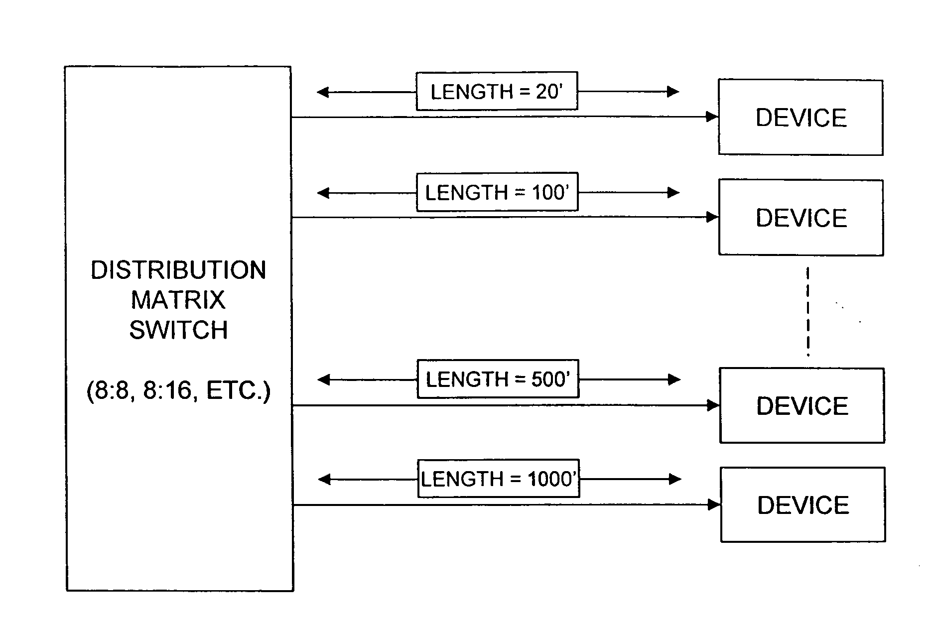
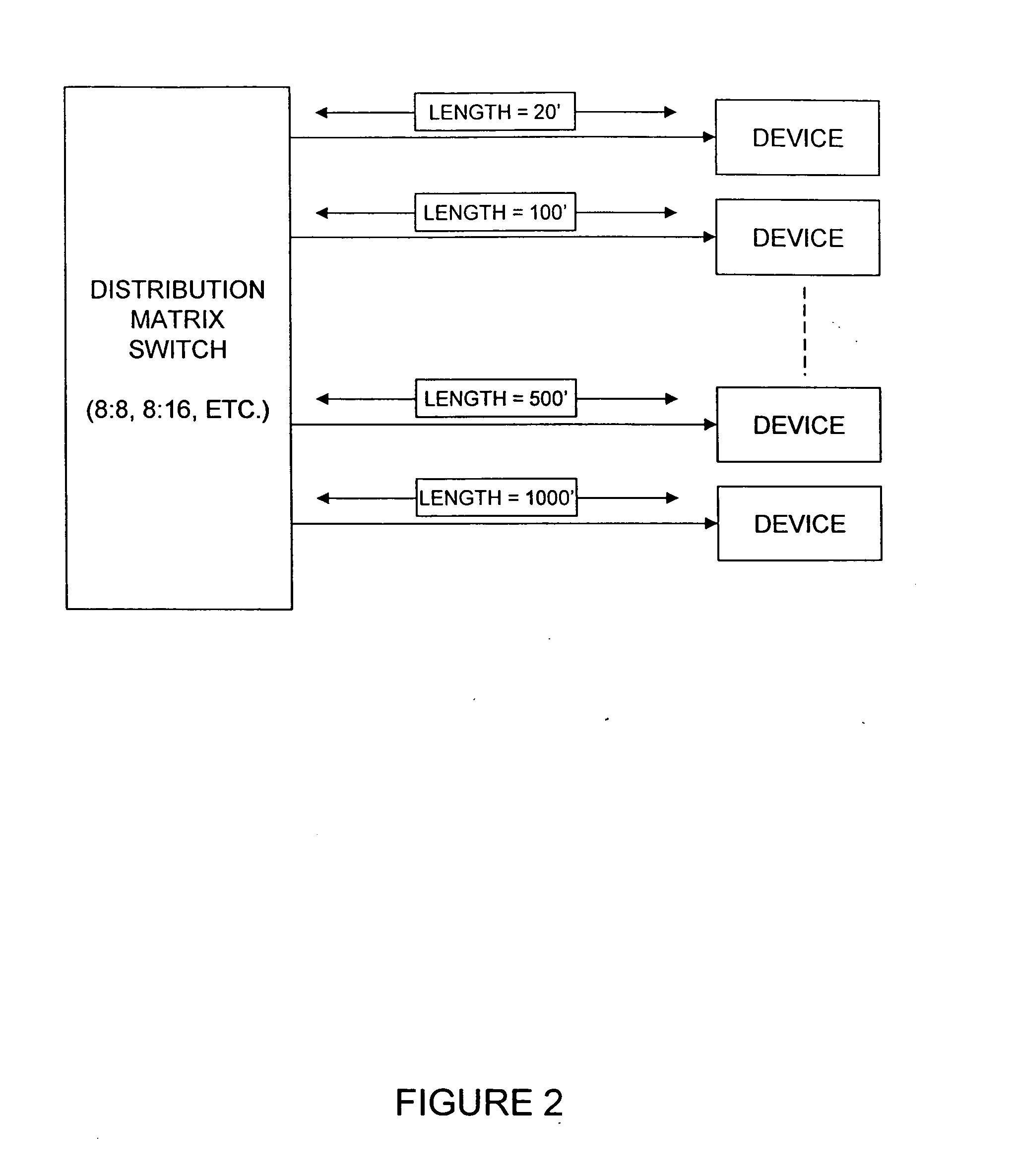
These matrix switches, however, do not provide for the challenges which arise when the distances between the matrix switch and the various output devices varies.
An additional challenge with the standard matrix switch device arises with the growing popularity of using inexpensive cabling, such as the twisted pair cable referred to as CAT-5 cable.
While this cable is shielded, and may be readily available and rather inexpensive, it often introduces significant line loss when used on long length applications.
In fact, a 1000 foot length of cable used on an installation may introduce a thirty percent loss in signal strength, with the higher frequency signals being most significantly reduced.
This is particularly problematic in applications where high frequency signal quality is crucial to system performance.
However, such amplification is expensive to implement, and requires a careful calibration of the system based on wire length and signal strength.
Moreover, because installations of these high end video and audio distribution systems are often made using unskilled or inattentive workers, such solutions are seldom effective.

Method used


Image

  • Audio video matrix switch with automatic line length signal compensator
  • Audio video matrix switch with automatic line length signal compensator
  • Audio video matrix switch with automatic line length signal compensator

Examples


Embodiment Construction

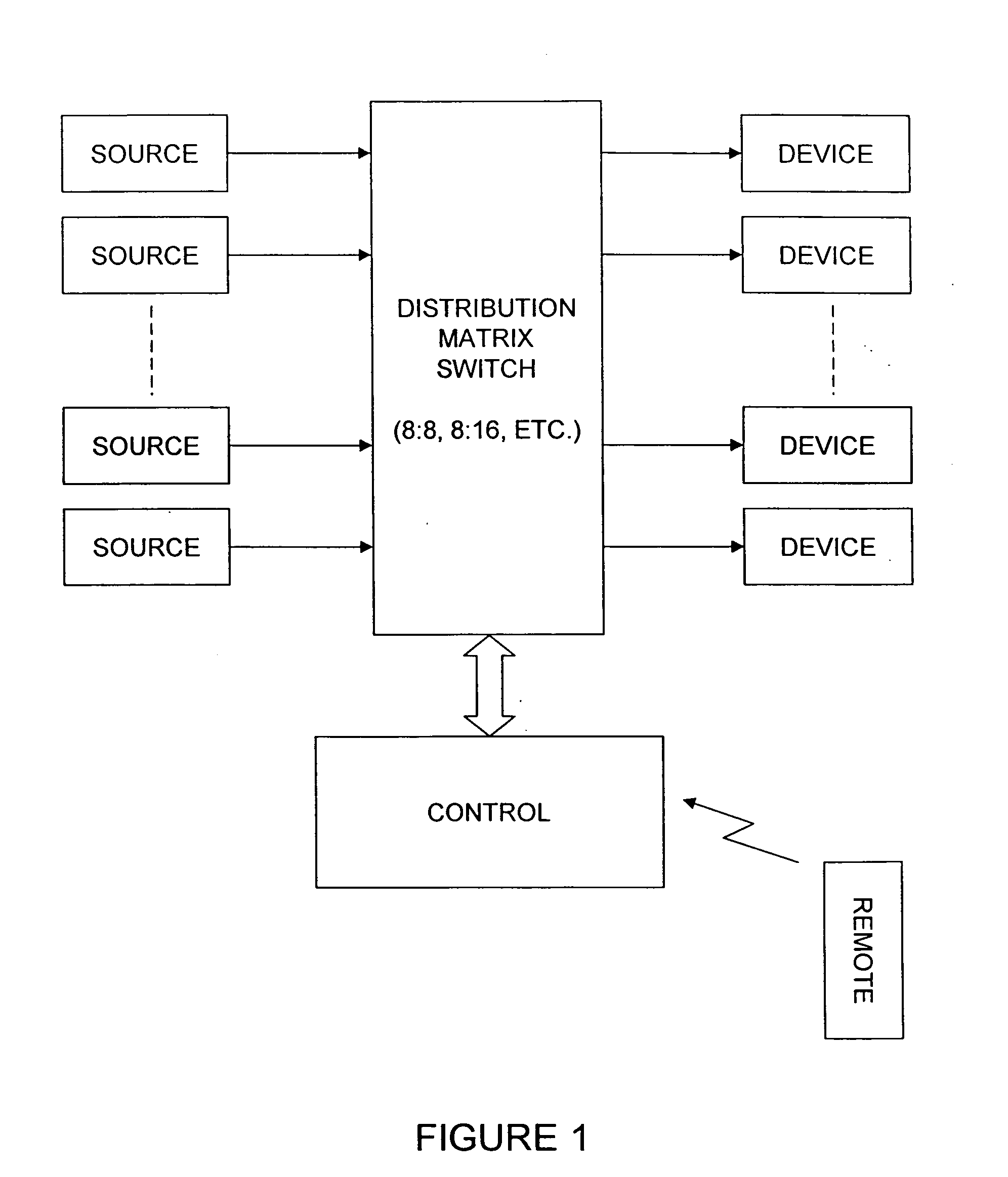
[0018]Referring now to FIG. 3, an exemplary audio and video distribution system of the present invention is shown and generally designated 100. System 100 includes a plurality of sources 102 feeding audio and video signals to a distribution matrix switch 104 configured to provide a plurality of output devices 108 with the desired input signals. These desired signals are passed through a differential signal receiver and equalizer module 106 which receives the routed signal from the matrix switch 104, determines the cable length, and provides a compensation signal used to compensate the audio and video signals for signal degradation resulting from the cable length. The differential audio and video signal module 106 then provides an audio and video signal to the output device 108.

[0019]In a preferred embodiment, the differential signal receiver and equalizer module of the present invention is designed to fit into a single gang wall outlet box for ease of installation, and includes outp...


PUM


Abstract

An audio video matrix switch with automatic line length signal compensator provides for the determination of the line length and an automatic compensation signal to be generated, and for that compensation signal to be used to provide an equalizing gain to the transmitted signal thereby providing a higher quality signal to the output device. A system of the present invention includes a matrix switch assembly receiving inputs from a plurality of audio and video signal sources, and a plurality of audio and video output device. Each of the video output devices is equipped with a differential signal receiver and equalizer module which receives a routed signal from the matrix switch, determines the cable length, and provides a compensation signal to the audio and video signals to compensate for the cable length, and provides that compensated signal to an output device.

Description

RELATED APPLICATION[0001]This application claims the benefit of priority to U.S. Provisional Patent Application Ser. No. 60 / 967,741 by the same inventor, filed Sep. 5, 2007, and currently co-pending.FIELD OF THE INVENTION[0002]The present invention relates generally to audio and video distribution equipment. The present invention is more particularly, though not exclusively, applicable to an audio video distribution system which receives multiple signal inputs from multiple sources, and routes these signals to multiple audio video devices.BACKGROUND OF THE INVENTION[0003]Audio and video equipment continues to improve in quality, durability, and versatility. These improvements include an increasingly higher quality video signal, clearer audio signals, and an overall decrease in the cost of high performance equipment. Due to this trend, it has become increasingly common to have an assortment of audio and video signal sources, matched with an assortment of audio and video signal output...

Claims


Application Information

Patent Timeline
IPC IPC(8): H04N21/60
CPCH04B3/06H04N7/104H04N5/268
Inventor PAUL, BILL
Owner PAUL BILL
Learn More