
Ultrasonographic diagnostic system and ultrasonic diagnostic device

a diagnostic system and ultrasonic technology, applied in tomography, instruments, using reradiation, etc., can solve the problems of difficult to express objective information using palpation, displacement measurement using ultrasonic wave has become an important technical issue, and the difficulty of palpation requires experienced doctors, etc., to achieve high spatial resolution and high precision

Active Publication Date: 2011-11-03
CANON KK
View PDF1 Cites 37 Cited by
  • Summary
  • Abstract
  • Description
  • Claims
  • Application Information

AI Technical Summary

Benefits of technology

[0057]As described above, the present invention achieves two-dimensional displacement distribution measurement and two-dimensional velocity distribution measurement with high spatial resolution and high precision.

Problems solved by technology

However, it is difficult to express objective information using palpation and palpation requires experienced doctors.
Hence, in recent ultrasonic diagnostic devices, such displacement measurement using ultrasonic wave has become an important technical issue.
However, generally, it is difficult to estimate the direction of displacement at each portion in advance, which results in an error caused by the estimated direction.
However, this method suffers from a practical problem because it requires a transducer element array with a large aperture.
An aperture of a transducer element array actually usable therefor has disadvantages such as limited visual field and insufficient precision provided by velocity composition.
Further, an interval between scan lines of ultrasonic beams is relatively large.
However, the number of data sampling becomes enormous, with the result that the two-dimensional speckle tracking method cannot be implemented in the scale of the conventional ultrasonic diagnostic devices.
Thus, the two-dimensional speckle tracking method is only applicable to detection of motion of a tissue portion displaced relatively greatly, disadvantageously.
However, in this method, spatial resolution is decreased, disadvantageously.
This makes it difficult to implement the method in a conventional ultrasonic diagnostic device, disadvantageously.

Method used


Image

  • Ultrasonographic diagnostic system and ultrasonic diagnostic device
  • Ultrasonographic diagnostic system and ultrasonic diagnostic device
  • Ultrasonographic diagnostic system and ultrasonic diagnostic device

Examples


first embodiment

[0106]The present embodiment relates to a device (system) for finding two-dimensional displacement distributions before and after applying pressure to a subject, so as to measure a two-dimensional strain distribution.

[0107]FIG. 3 shows a configuration of the present embodiment.

[0108]An ultrasonic diagnostic device (system) in FIG. 3 includes an ultrasonic probe 11, a pulse generator 12, a transmission beam former 13, amplifiers 14, a control unit 16, a reception beam former 15, a detecting unit 90, and a display device 26. Transmission beam former 13 and reception beam former 15 constitute a beam forming unit 91.

[0109]Detecting unit 90 includes an echo signal allocating unit 17, an echo signal sequence storage unit 18, an orthogonal detector 19, a correlation calculating unit 20, a hyperbola direction displacement calculating unit 21, an ellipse direction displacement calculating unit 22, a coordinate converting unit 23, a coordinate converting unit 24, and a two-dimensional displac...

second embodiment

[0145]In the first embodiment, when the number of sampling points is increased to improve spatial resolution for the two-dimensional displacement distribution, it takes a longer time until the displacement distribution is displayed because transmission / reception need to be done for all the sampling points. In the present embodiment, all the reception signal data are stored which are received by the transducer elements of the ultrasonic probe in response to sequential transmission from the transducer elements of the transducer element array. In accordance with the data thus stored, beam forming is performed by means of calculation to form a beam conforming to the substantial hyperbola. Accordingly, an echo reception signal sequence conforming to the substantial hyperbola is formed.

[0146]In other words, this embodiment provides an example characterized in that the ultrasonic probe focuses the ultrasonic wave by aperture synthesis achieved by ultrasonic transmission by at least one or ...


PUM


Abstract

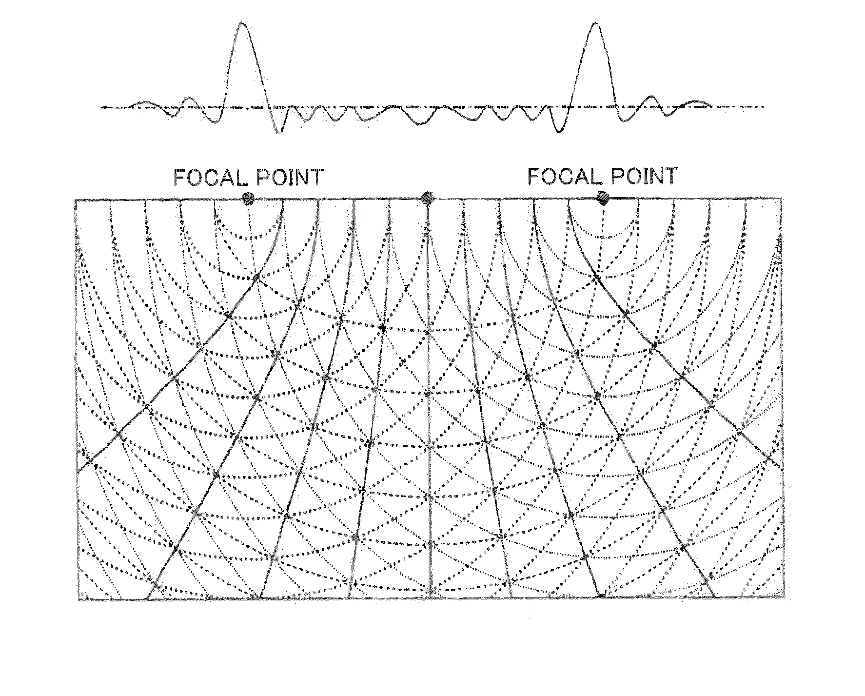
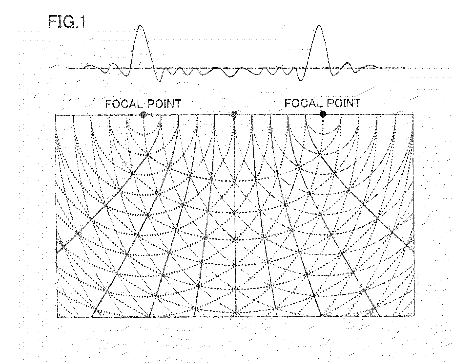
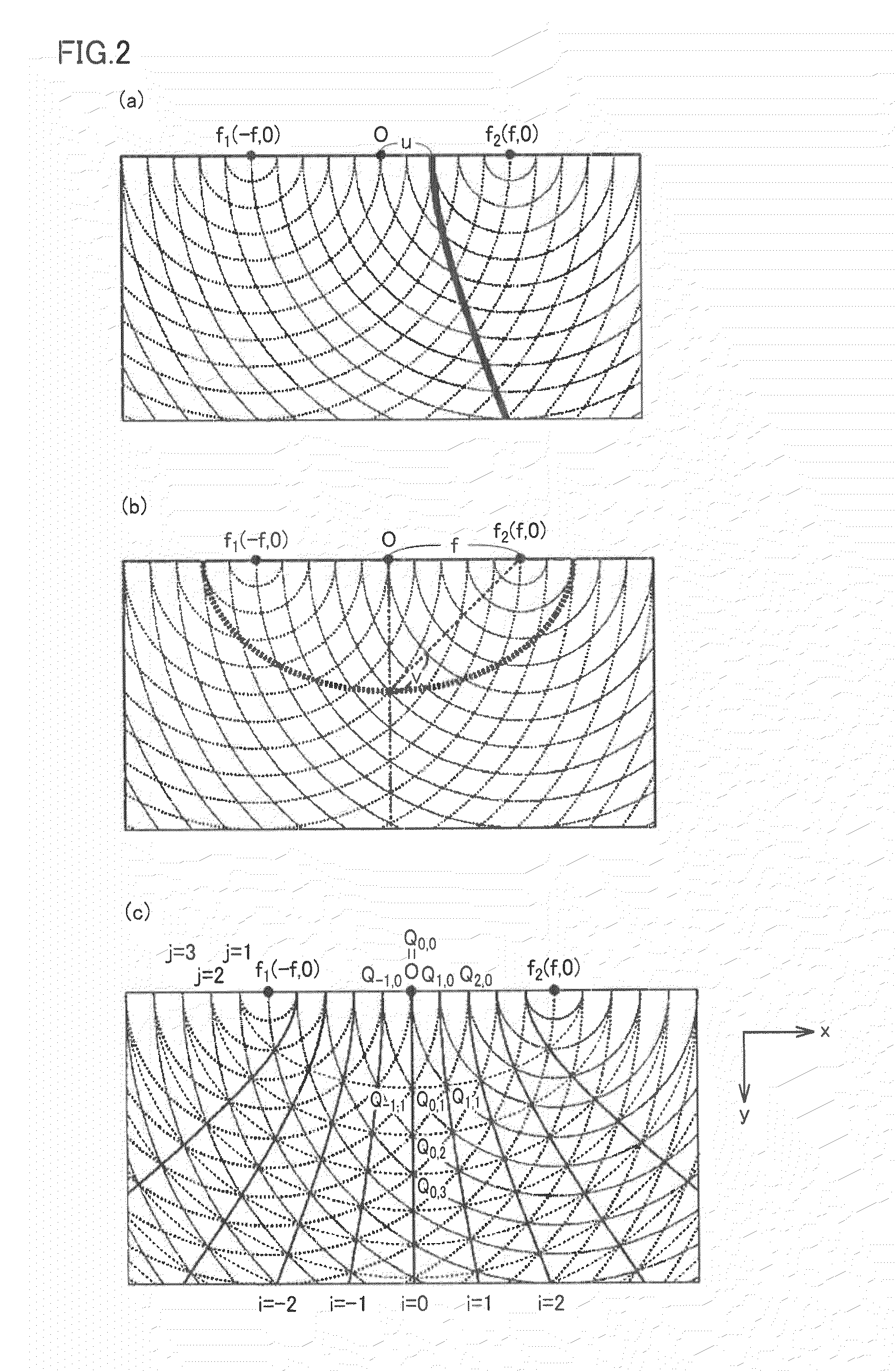
An ultrasonic probe is constituted by ultrasonic transducer elements arranged in a direction. A beam forming unit forms acoustic field sensitivity modulated in a direction substantially orthogonal to scan lines in a subject by focusing an ultrasonic wave on a sequence of sampling points existing along the scan lines, and applying delay and apodization on a transmission / reception signal of each of the ultrasonic transducer elements. A detecting unit detects displacements at each sampling point in a direction tangential to the scan lines and in a direction tangential to curves substantially orthogonal to the scan lines by arithmetic between reception signals for the sampling point at different time points. Each curve of the curves substantially orthogonal to the scan lines is constituted by a sequence of points for which a total of times taken for ultrasonic pulses to reach from two points fixed to the ultrasonic probe is substantially the same.

Description

TECHNICAL FIELD[0001]The present invention relates to an ultrasonic diagnostic system and an ultrasonic diagnostic device.BACKGROUND ART[0002]Recent ultrasonic diagnostic devices have a function of displaying an ultrasonic tomographic image (B mode image) obtained from a reflected echo resulting from a difference in reflectivity between tissues to indicate a tissue structure in a living body, as well as a function of measuring a blood flow velocity and a blood flow rate in a blood vessel and a heart using ultrasonic Doppler blood flowmetry or measuring a velocity or amount of motion of tissue portions such as motion of a cardiac wall and displaying information about them.[0003]Further, recently, ultrasonic waves have begun to be used to measure hardness of tissue portions for tissue diagnosis. This is because hardness, i.e., an elastic property in a rough area is deeply associated with its pathological state. For example, it is known that a disease area is harder than a normal tissu...

Claims


Application Information

Patent Timeline
Patent Type & Authority Applications(United States)
IPC IPC(8): A61B8/14
CPCA61B8/08G01S7/52042G01S15/8984G01S15/8927G01S7/52046G01S7/5209
Inventor SHIINA, TSUYOSHI
Owner CANON KK
Learn More