Eureka AIR delivers breakthrough ideas for toughest innovation challenges, trusted by R&D personnel around the world.

Communication system, subscriber accommodating apparatus and communication method

a communication system and subscriber technology, applied in multiplex communication, optics, instruments, etc., can solve the problems of large data size downloaded from the web, normal conflicting requirements, and inferior stability of packet communication networks to synchronous communication networks, so as to reduce packet loss and reduce packet loss. the effect of path switching operation and shortened switching time of working system and protection system in packet communication networks

Inactive Publication Date: 2011-11-03
HITACHI LTD
View PDF3 Cites 59 Cited by
  • Summary
  • Abstract
  • Description
  • Claims
  • Application Information

AI Technical Summary

Benefits of technology

The patent text discusses the challenges faced by packet communication networks in terms of stability and flexibility. It highlights the need to increase the speed of switching between a working system and a protection system to reduce packet loss during switches. The invention aims to address this problem by increasing the switching speed of the network and reducing the likelihood of packet discard.

Problems solved by technology

On the other hand, the packet communication network is inferior in the stability of the path to the synchronous communication network.
Those requirements normally conflict with each other.
Also, data size downloaded from the web is large, and the line bandwidth is widened, resulting in a situation where a failure of partial packet transmission enlarges a transmission time, which can be also sensuously recognized by the user.
When a communication failure occurs in a path being used, no path temporarily exists in a time required for the control packet analysis and the path switching process, resulting in a possibility that parts of the packet are discarded.

Method used


Image

  • Communication system, subscriber accommodating apparatus and communication method
  • Communication system, subscriber accommodating apparatus and communication method
  • Communication system, subscriber accommodating apparatus and communication method

Examples


first embodiment

[0126]3. Operation of First Embodiment

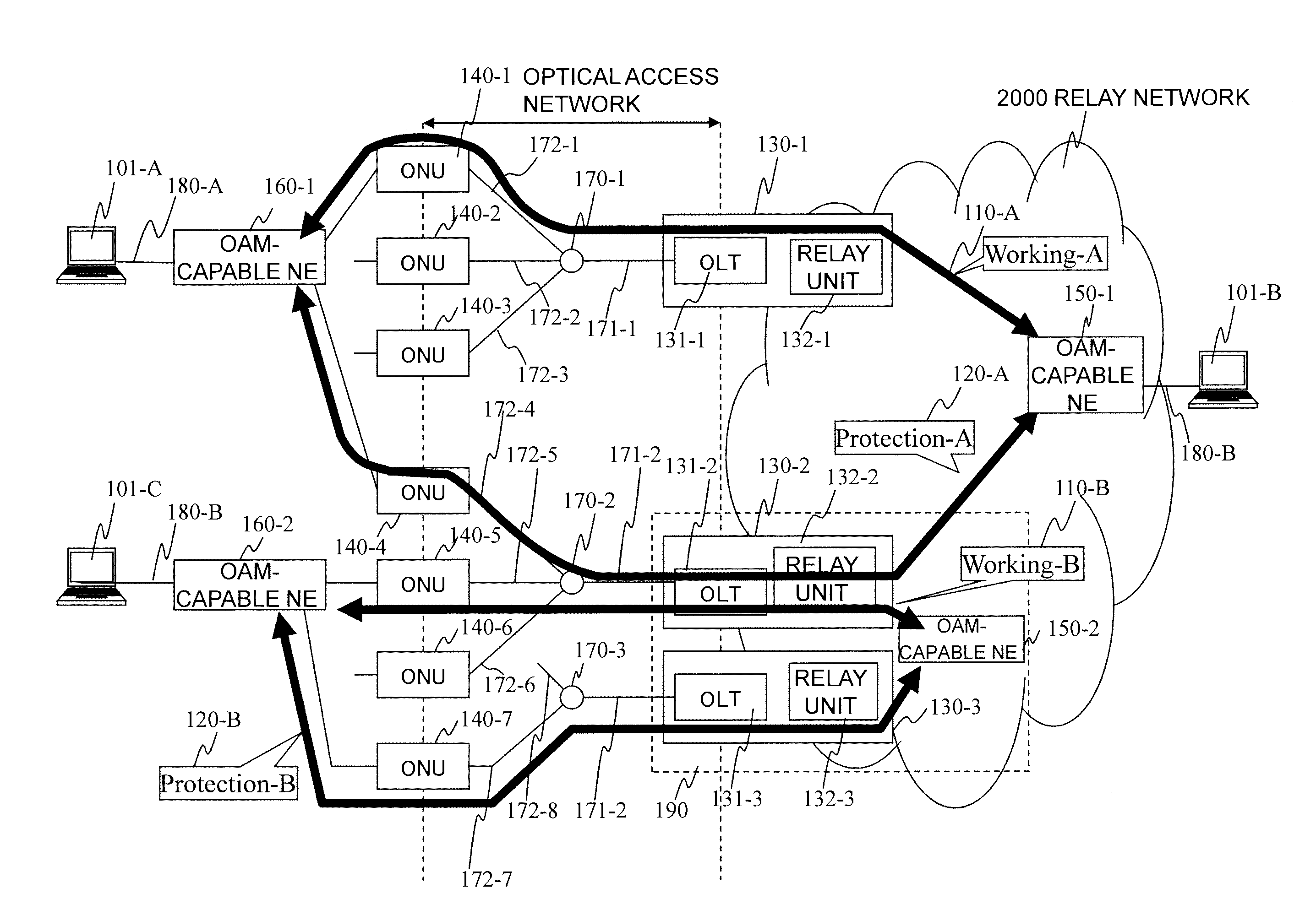
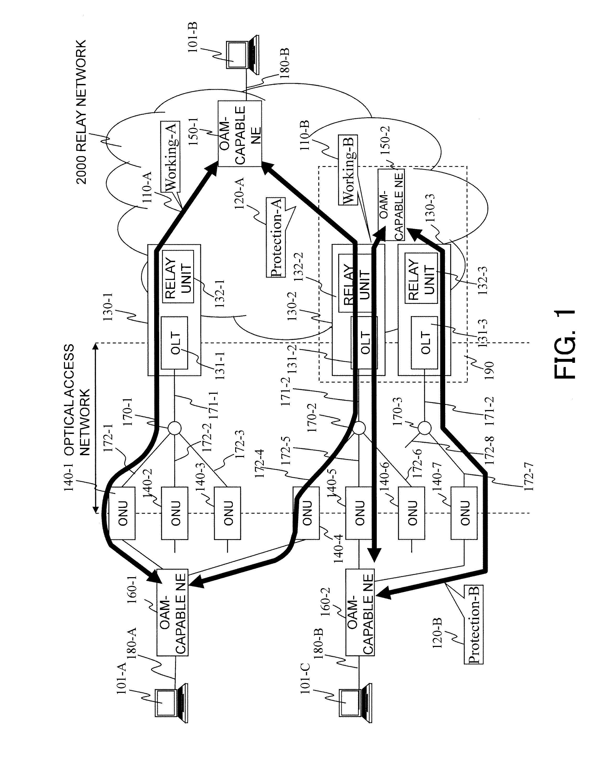
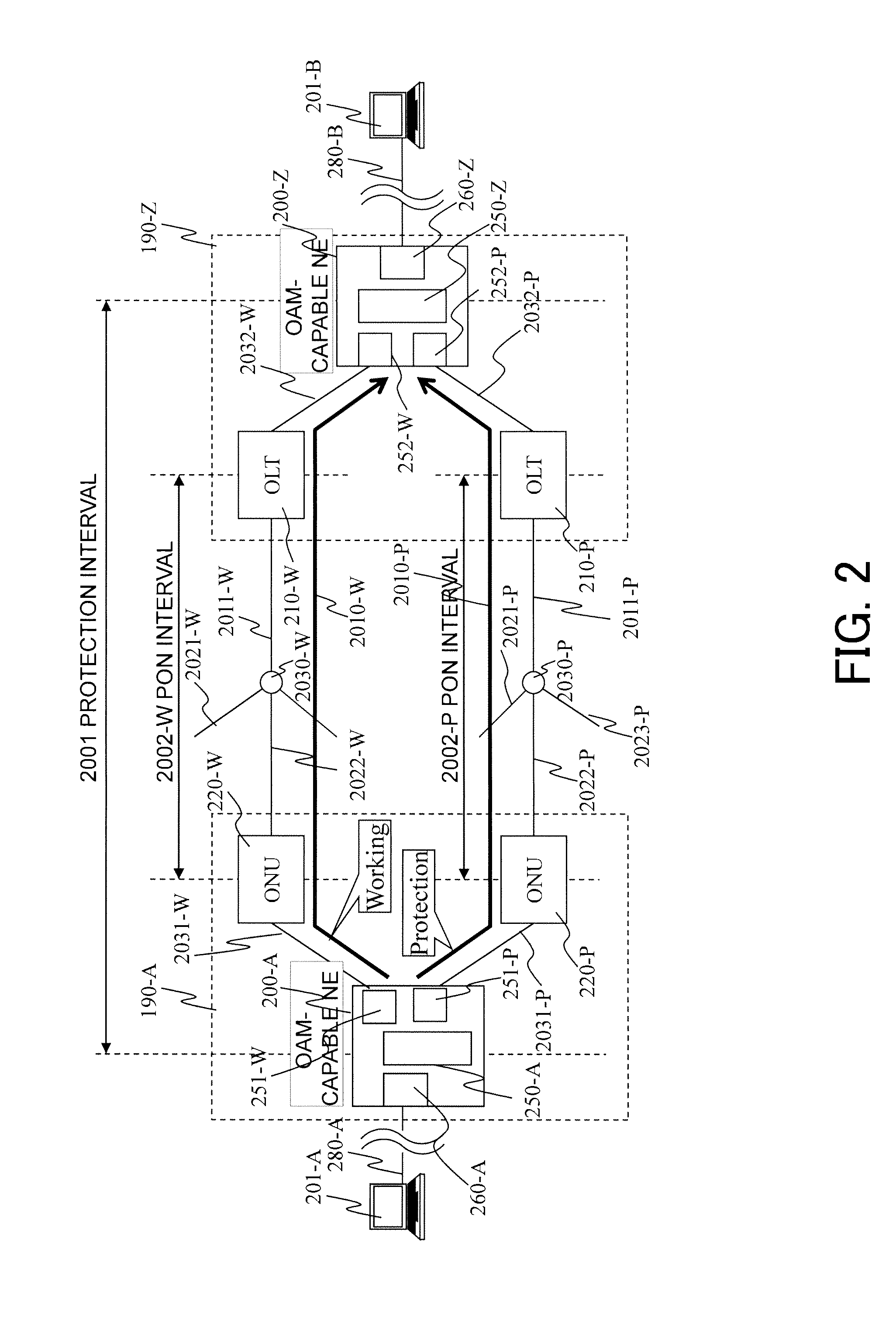
[0127]The feature of this configuration resides in that a part of the protection interval 2001 is configured by the PON interval. Therefore, the operation of switching communication path is conducted by the aid of a fact that the reciprocating communication time in the PON interval is grasped by the OLT, which is the feature of the PON.

[0128]In the path redundant function over the existing packet communication network (for example, Non Patent Literature 6), the operation of switching to the protection system starts first after a reception failure of plural continuity check message (CCM) frames 301-1 and 301-2 (and subsequently transmitted CCM frames) has been confirmed, which is observed after the communication failure occurs. This procedure is conducted taking a fact that the packet (frame) transmission time within the packet communication network is not constant but varies with a given time width into consideration. However, when the protectio...


PUM


Abstract

Switching process at the occurrence of a path trouble is performed more quickly to reduce the number of packet discards during a traffic transition from a currently used system path to a standby system path within a section to be protected. An OLT (210-W) refers to the DBA information of a PON section and, if receiving no CCM frame at a timing at which the same should be received, then determines that some trouble has occurred on the path (S801) and transmits, to an OAM-compliant NE (200-Z), an application-for-switching frame (1501) to notify the OAM-compliant NE (200-Z) of the abnormal condition. The OAM-compliant NE (200-Z) monitors the occurrence of the trouble within the PON section nearly in real time, starts a switching process (S802) and generates and transmits a standby-system delivery request (321) (S302, S803). An OAM-compliant NE (200-A) switches the communication path to the standby-system passing through an OLT (210-P).

Description

TECHNICAL FIELD[0001]The present invention relates to a communication system and a communication apparatus, and more particularly to a communication system and a communication apparatus which reduce a communication stop time occurring during operation of switching between a working communication path and a protection communication path to improve availability of the communication system and the communication apparatus.BACKGROUND ART[0002]In general, with an increasing demand for a broadband, as user access lines, implementation of large-capacity access lines has been advanced instead of a communication technology based on a telephone line such as a digital subscriber line (DSL). At present, in the optical access lines, a passive optical network (PON) system that can share optical fibers with plural subscribers has been frequently used from line construction costs and maintenance management costs. The PON system that multiplexes traffics flowing between a plurality of users and a sta...

Claims


Application Information

Patent Timeline
Patent Type & Authority Applications(United States)
IPC IPC(8): H04B10/08
CPCH04L43/0852H04L45/22H04L45/28H04J14/0227H04Q2011/0081H04L43/0817H04Q11/0067H04L45/243
Inventor MIZUTANI, MASAHIKOYAJIMA, YUSUKEYAMAMOTO, NOBUYUKIASHI, YOSHIHIRO
Owner HITACHI LTD
Why Eureka
Eureka Blog
Learn More