Airbag housing of an airbag system, and airbag system

a technology of airbag system and airbag housing, which is applied in the direction of pedestrian/occupant safety arrangement, vehicular safety arrangment, vehicle components, etc., can solve the problems of large construction space, increased components, and severe load on the vehicle seat and on the vehicle occupant, so as to increase the safety and increase the reliability of the airbag system, and the effect of rapid and cost-effective production

Active Publication Date: 2011-11-03
DR ING H C F PORSCHE AG
View PDF9 Cites 0 Cited by
  • Summary
  • Abstract
  • Description
  • Claims
  • Application Information

AI Technical Summary

Benefits of technology

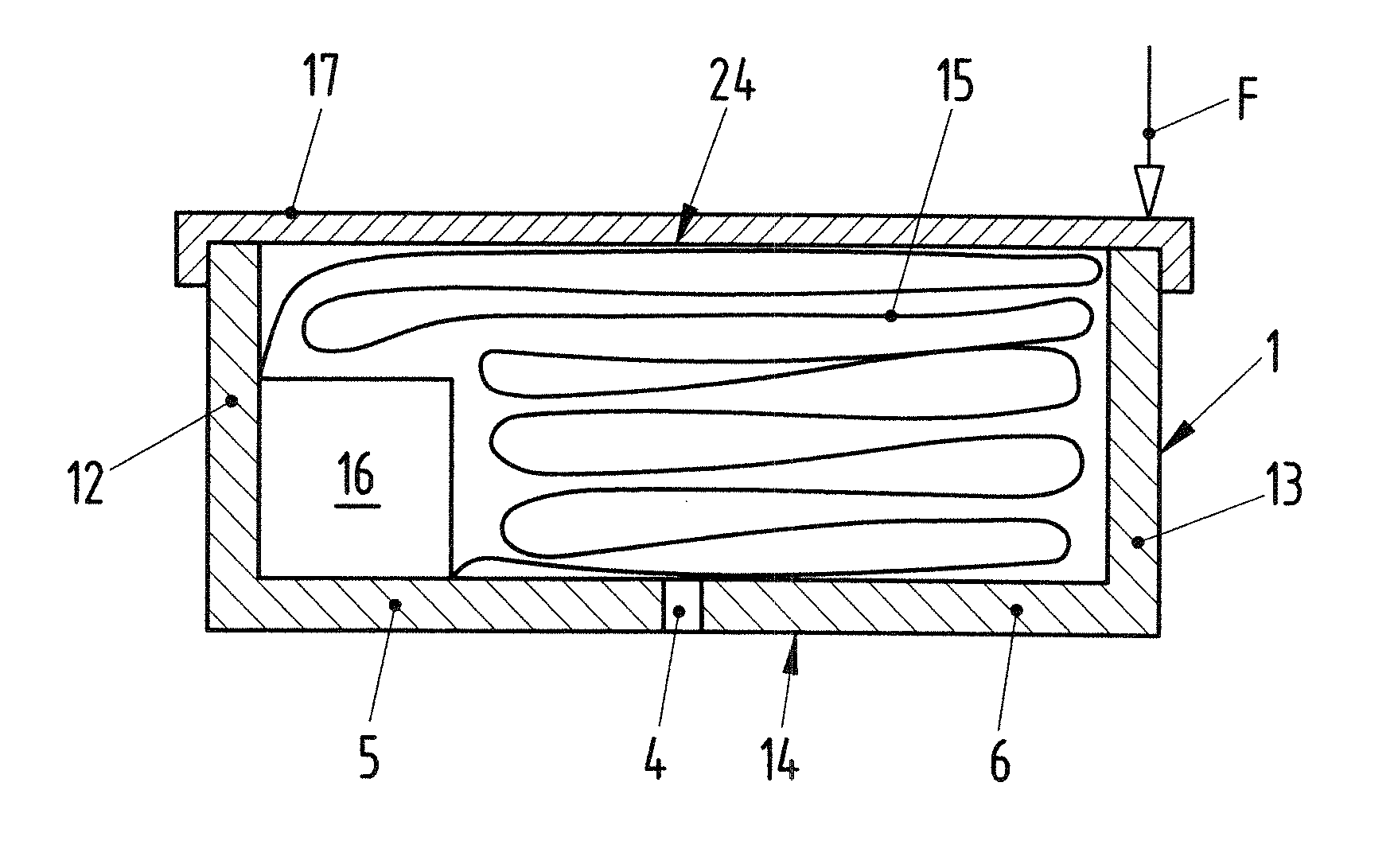
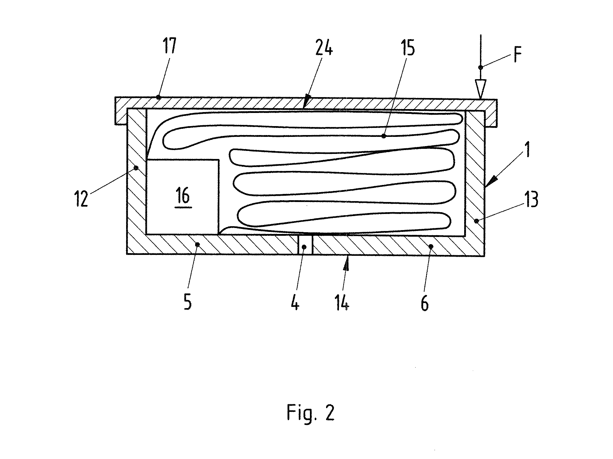
[0012]The defined bending region preferably is designed so that action of the mechanical load on the airbag housing plastically deforms the bending region. The plastic deformation absorbs a particularly high deformation energy, thus increasing the reliability of the airbag housing.
[0022]The airbag housing preferably is connected operatively to a seat structure of a seat in such a manner that, by means of the deformation of the defined bending region, a free space between the deformed seat structure and the airbag housing upon deformation of the seat structure is filled at least partially by the deformed airbag housing. Thus, deformation energy is additionally input, thereby increasing the safety and reliability of the airbag system.

Problems solved by technology

This results in a severe load on the vehicle seat and on the vehicle occupant.
Furthermore, a possible free space between the nondeformable side airbag and the deformable seat structure is not used, since the housing of the side airbag is very stiff.
However, this approach is disadvantageous in that a relatively large construction space must be made available and additional components in the form of the U profile and additional fasteners are required.
This increases the outlay on production and reduces the possible area of use of this type of side airbag system.

Method used


Image

  • Airbag housing of an airbag system, and airbag system
  • Airbag housing of an airbag system, and airbag system
  • Airbag housing of an airbag system, and airbag system

Examples


second embodiment

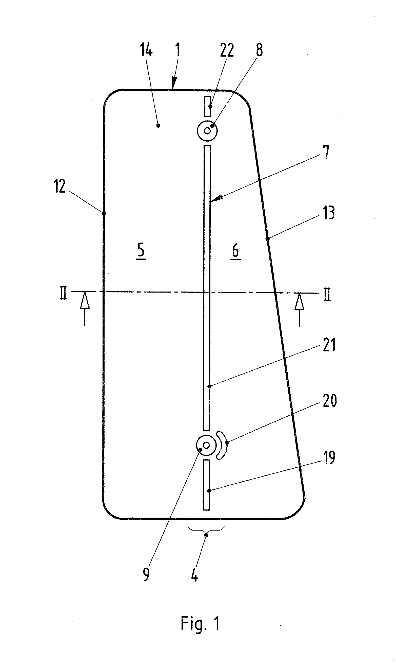
[0035]FIG. 4 shows, in a sectional view, the airbag housing 1, wherein the defined bending region is designed as a weakening of a wall thickness d of the housing 1. For this purpose, the wall thickness d of the airbag housing 1 is reduced in the region of the envisaged bending region 4 to a wall thickness t to define the bending region 4. The wall thickness d may be reduced, for example as shown in FIG. 3, on both sides or only on one side. The reduction in the wall thickness may be achieved, for example, by milling or eroding. The remaining wall thickness t is dependent on the predetermined threshold value that is intended to be achieved. In a manner similar to the recess 7FIG. 1, the reduction in the wall thickness d to the wall thickness t can be interrupted in sections by material bridges having the original wall thickness d of the airbag housing. This achieves sufficient stability of the bending region 4 and the bending behavior of the bending region 4 can be adjusted convenien...

third embodiment

[0036]FIG. 5 shows the airbag housing 1 where the defined bending region 4 is formed from a material differing from a basic material of the housing 1. In this embodiment, the material of the defined bending region 4 preferably has greater ductility than the basic material of the airbag housing 1. In the airbag housing 1 of FIG. 5, the bending region 4 is designed, for example, as a joint 4 between the first and second housing sections 5 and 6. The joint 4 may protrude over surfaces of the base 14 of the airbag housing 1, as illustrated in FIG. 5, or may end flush with said surfaces. For example, the first and the second housing section 5, 6 may be designed as sheet-metal components, wherein the defined bending region 4 is formed from a preferably plastically deformable plastics material. In this embodiment, the airbag housing 1 advantageously can be assembled in a plastics injection molding process, in which the sheet-metal parts 5, 6 are placed into an injection mold and the plasti...


PUM


Abstract

An airbag housing (1) of an airbag system (3), in particular of a side airbag system (3) of a motor vehicle, has a defined bending region (4) formed by a specific weakening of the material of the airbag housing (1) and is configured so that, on action of a mechanical load (F) on the airbag housing (1) above a predetermined threshold value, the airbag housing (1) absorbs deformation energy by deformation of the defined bending region (4).

Description

CROSS REFERENCE TO RELATED APPLICATION[0001]This application claims priority under 35 USC 119 to German Patent Application No 10 2010 016 749.5 filed on May 3, 2010, the entire disclosure of which is incorporated herein by reference.BACKGROUND OF THE INVENTION[0002]1. Field of the Invention[0003]The invention relates to an airbag housing of an airbag system, in particular of a side airbag system of a motor vehicle, and to an airbag system having an airbag housing of this type.[0004]2. Description of the Related Art[0005]The present invention is usable on any vehicle, but the invention and the problem on which the invention is based are explained in more detail herein with reference to a passenger motor vehicle.[0006]Modern motor vehicles have a side airbag fastened to the seat side part and inflated in the event of a side crash. The side airbag is located between the vehicle seat and a vehicle structure that intrudes into the passenger compartment. However, due to the geometry of th...

Claims


Application Information

Patent Timeline
Patent Type & Authority Applications(United States)
IPC IPC(8): B60R21/16
CPCB60R21/207B60R21/055
Inventor HEINISCH, MARKUSPIEPER, MARC-HAYUNGKEDING, BASTIANRUECKERT, FLORIAN
Owner DR ING H C F PORSCHE AG
Why Eureka
Try Eureka