
Orthopaedic Safety System

a safety system and orthopaedic technology, applied in the field of orthopaedic safety system, can solve the problems of excessive bone strength, intraoperative morbidity, hoop stress in the bone, etc., and achieve the effects of improving signal-to-noise ratio, increasing measurement resolution, and increasing the error rate of the sensor member

Inactive Publication Date: 2011-10-27
SILESCO
View PDF6 Cites 49 Cited by
  • Summary
  • Abstract
  • Description
  • Claims
  • Application Information

AI Technical Summary

Benefits of technology

[0036]When measuring the strain in a bone during a procedure, the one or more output signals are typically relatively low-level voltage signals. This may render the sensor member particularly susceptible to noise from other electrical devices, thus increasing the error rate of the sensor member. Accordingly, the sensor member may further include a shielding member to shield said noise.
[0037]Still further, the sensor member may comprise an amplifier. The processed signal of the strain member is relatively small and typically less than 10 mV / V (10 mV of output per volt of excitation voltage). The amplifier typically amplifies the signal level to increase measurement resolution and improve signal-to-noise ratios.
[0038]Further, the sensor member may include a filtering means. The filtering means may remove high-frequency noise from other electrical equipment.
[0042]Further, each bridging member may comprise an electrical conductor. Breaking of a bridging member may increase. the resistance across the circuit formed by the members. Each bridging member may also vary in thickness and / or material such that the increase in resistance upon breaking of one bridging member may differ from the increases in resistance due to the breaking of another member.
[0091]In a further embodiment, the endplates of the main body may be separated by at least one buckling member. Said one or more buckling member may buckle when the force limiting device is subjected to the pre-determined force. Such buckling of the buckling member(s) may limit the forces transmitted by said force limiting member to the implant such that the further transfer of force is prevented.
[0093]The driving member may comprise both an indicator member and a force limiting member. In this embodiment, the force indicator member may indicate a force in a first predetermined range and the force limiting member may prevent the transfer of a force in a second and greater range than said first pre-determined range.

Problems solved by technology

Particularly, one complication associated with the implant process is the formation of a longitudinal split in the bone known as a periprosthetic fracture (PPP) which results from hoop stress in the bone (created by insertion of the implant or broach or trial implant) exceeding the strength of bone.
PPFs are a significant cause of intraoperative morbidity and one of the most common causes of early post-operative failure of prosthetic components.
However, there still is surprisingly little in the orthopaedic literature regarding acetabular PPF at the time of surgery.
Further, the problem of intra-operative PPF in both the femur and acetabulum might be more prevalent than reported.
Whatever the incidence of intra-operative PPF the severity of the problem is highlighted by the poor outcomes reported.
Currently, there is no useful mechanism by which a surgeon can determine the risk of fracture both during and after an operative procedure.

Method used


Image

  • Orthopaedic Safety System
  • Orthopaedic Safety System
  • Orthopaedic Safety System

Examples


example 1

[0179](i) Co-ordinates of several landmarks are used to construct femoral and acetabular reference frames which are then exported as text files.

(ii) Co-ordinates of a tool tracker in the relevant reference frame (femoral or acetabular) are exported with associated time values, e.g

[0180]At t=t1, the tool tracker will be at co-ordinates; (x1, y1, z1).

[0181]Then t=t2 the tool tracker will be at co-ordinates (x2, y2, z2).

(iii) Data processing, the time based positions of the tool tracker are processed relative to the reference frames.

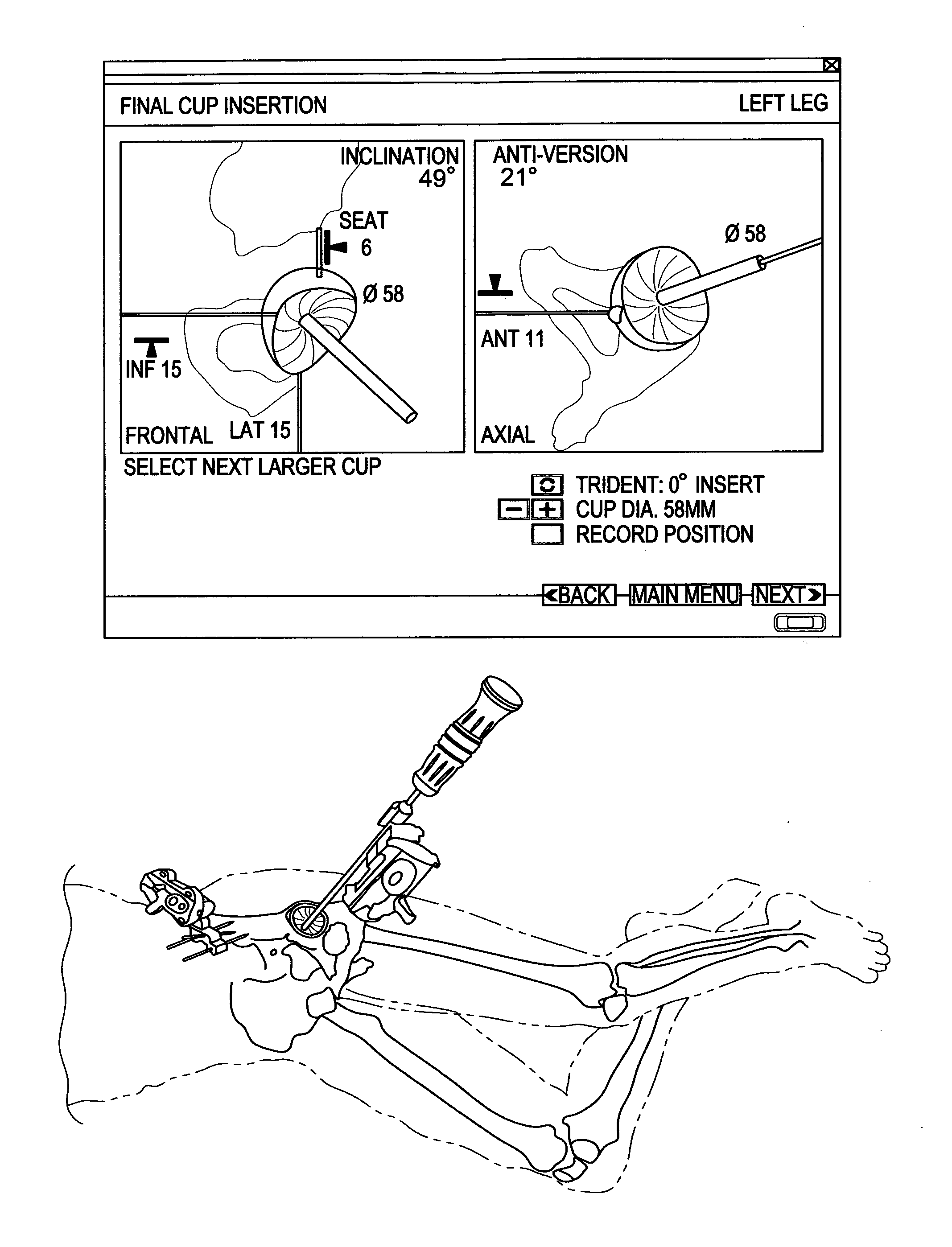
(iv) The relative velocity and relative acceleration of the components can be calculated. With the time based co-ordinates of the tool tracker and the relevant geometry of the component / implant obtained this enables a reconstruction of the relevant geometry of the prosthetic components, or a segment of the component that is of interest, for example the apex of the cup or the distal tip of the stem.

(v) The processed data is further processed comparatively ag...


PUM


Abstract

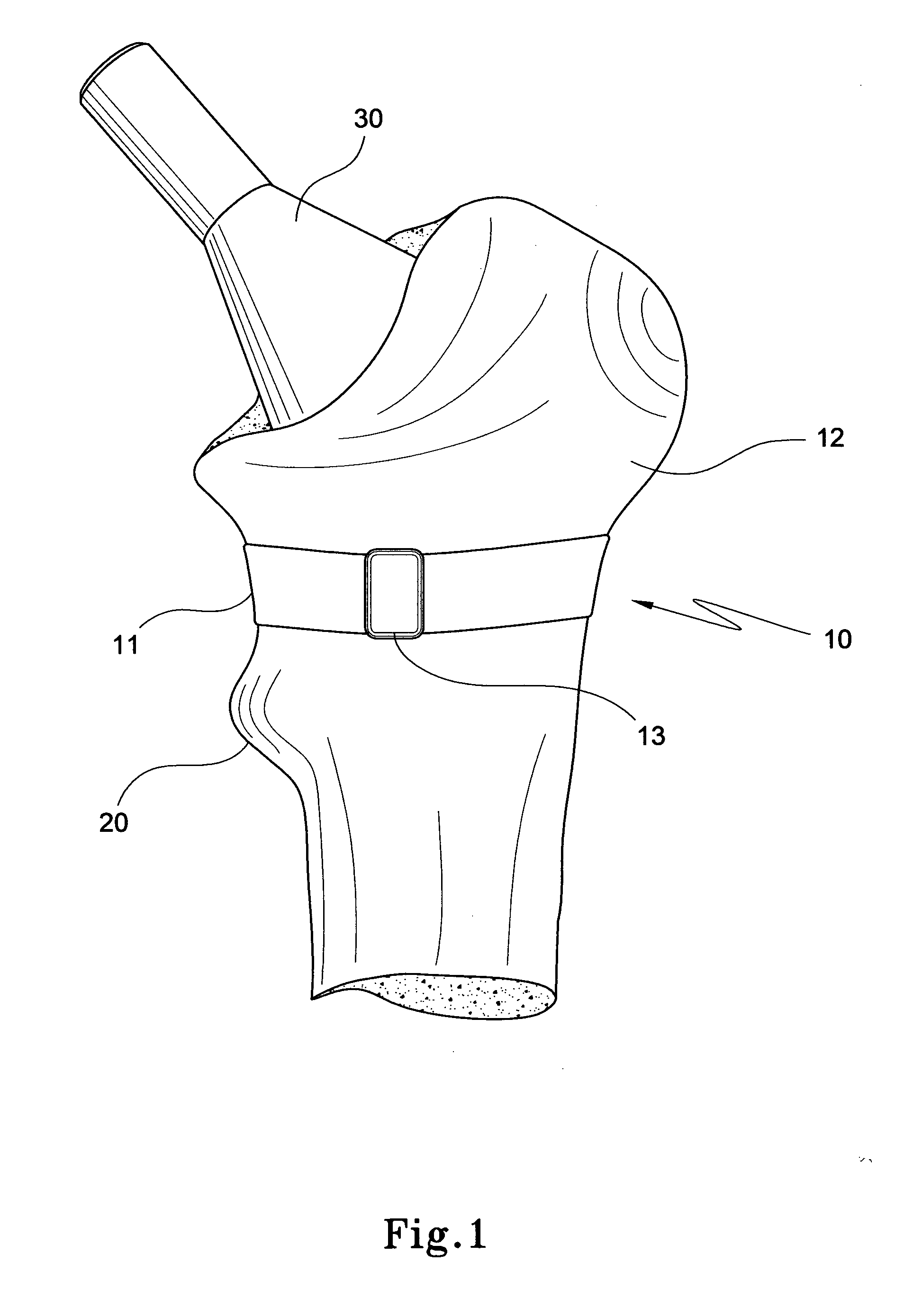
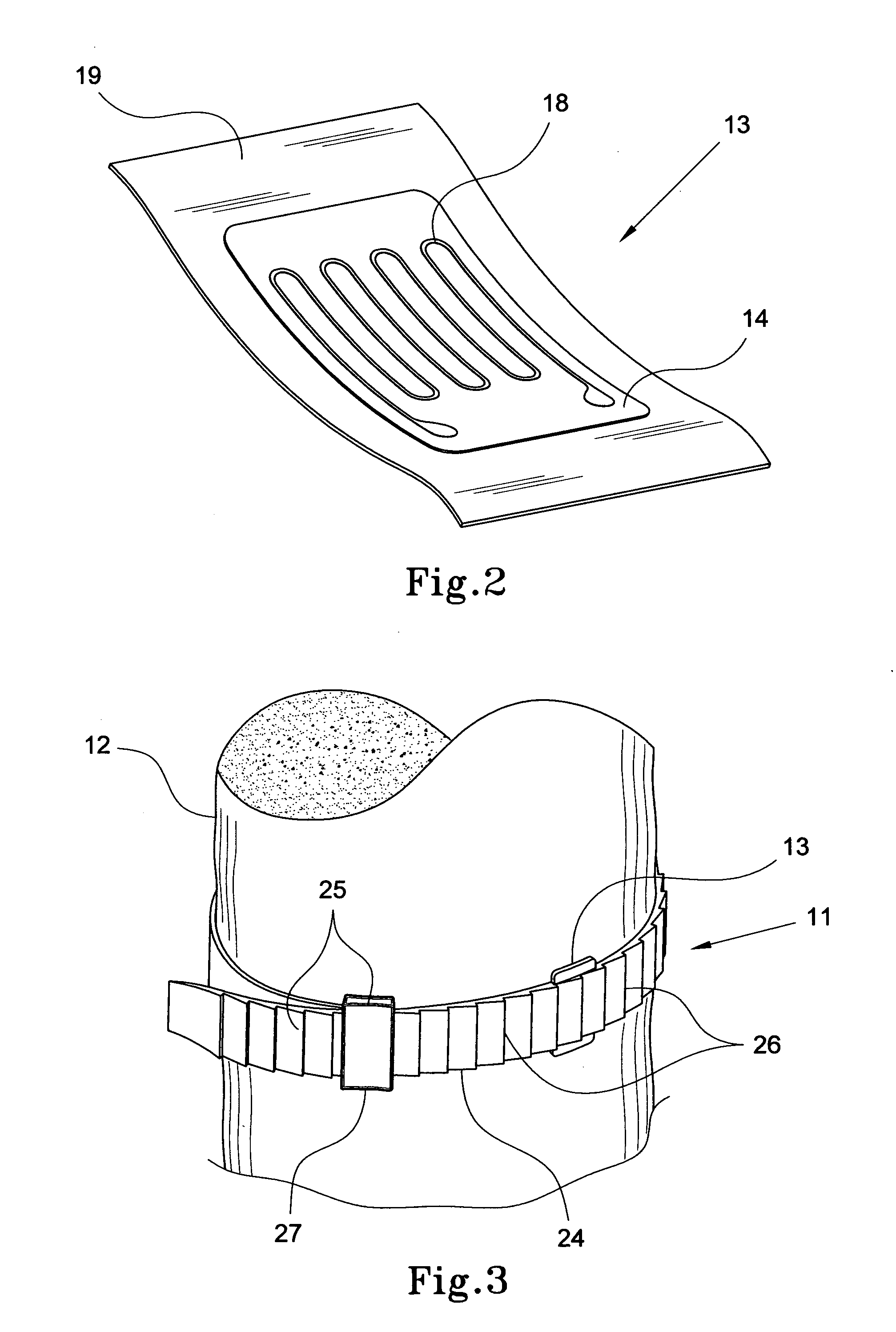
An orthopaedic device for generating one or more strain signals representative of the strain in a bone in response to a force applied to the bone. The device includes an encircling member (11) for encircling the bone of a subject and a sensor member (13) connected thereto, the sensor member including a strain sensor (14). In a preferred embodiment the strain sensor comprises one or more bridging members configured to break when subjected to a particular strain.

Description

CROSS-REFERENCE TO RELATED APPLICATIONS [0001]The present application claims priority from Australian Provisional Patent Application No 2008901009 filed on 29 Feb. 2008, Australian Provisional Patent Application No 2008901066 filed on 4 Mar. 2008, Australian Provisional Patent Application No 2008902854 filed on 5 Jun. 2008, the contents of which are incorporated herein by reference.FIELD OF THE INVENTION [0002]The present invention relates to a device for monitoring the strain in a bone to enable a user to evaluate the risk of fracture during or after an orthopaedic procedure.BACKGROUND ART [0003]Orthopaedic implants are typically mechanically hammered into position either through use of a mallet or a repetitive automated hammer. In both cases, force is applied by a mallet / hammer and through an impactor to an implant. Bone preparation typically uses a broach which may be hammered into the bone—the force being applied through a broach handle. On some occasions a trial implant may be ...

Claims


Application Information

Patent Timeline
IPC IPC(8): A61B5/103
CPCA61B5/4504A61B5/68A61B2562/0261A61F2/32A61F2002/4681A61F2002/30561A61F2002/30581A61F2002/4666A61F2/4657
Inventor WALTER, WILLIAM LINDSAYGILLIES, RONALD MARKDONOHOO, SHANE MCCARTHY
Owner SILESCO
Learn More