Neutron and multi-neutron generator

a multi-neutron generator and neutron technology, applied in nuclear reactors, nuclear engineering, greenhouse gas reduction, etc., can solve the problem that the nuclear fusion project of iter is expected to last for decades, and achieve the effect of increasing the flux density of neutrons

Inactive Publication Date: 2011-10-27
SCHMIDT WILLARD H
View PDF2 Cites 6 Cited by
  • Summary
  • Abstract
  • Description
  • Claims
  • Application Information

AI Technical Summary

Problems solved by technology

Deuterium-tritium plasma instability is a major problem, and the ITER nuclear fusion project is expected to last for decades.

Method used


Image

  • Neutron and multi-neutron generator
  • Neutron and multi-neutron generator
  • Neutron and multi-neutron generator

Examples


Embodiment Construction

The purpose of this invention is to produce neutrons and multi-neutron particles that can be used to stimulate nuclear reactions in other nuclear systems, and to provide the means for releasing nuclear binding energy in certain nuclear configurations for commercial and industrial applications.

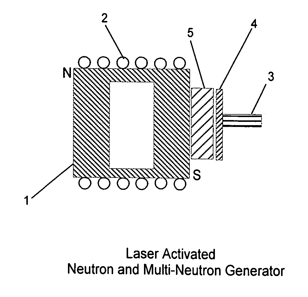
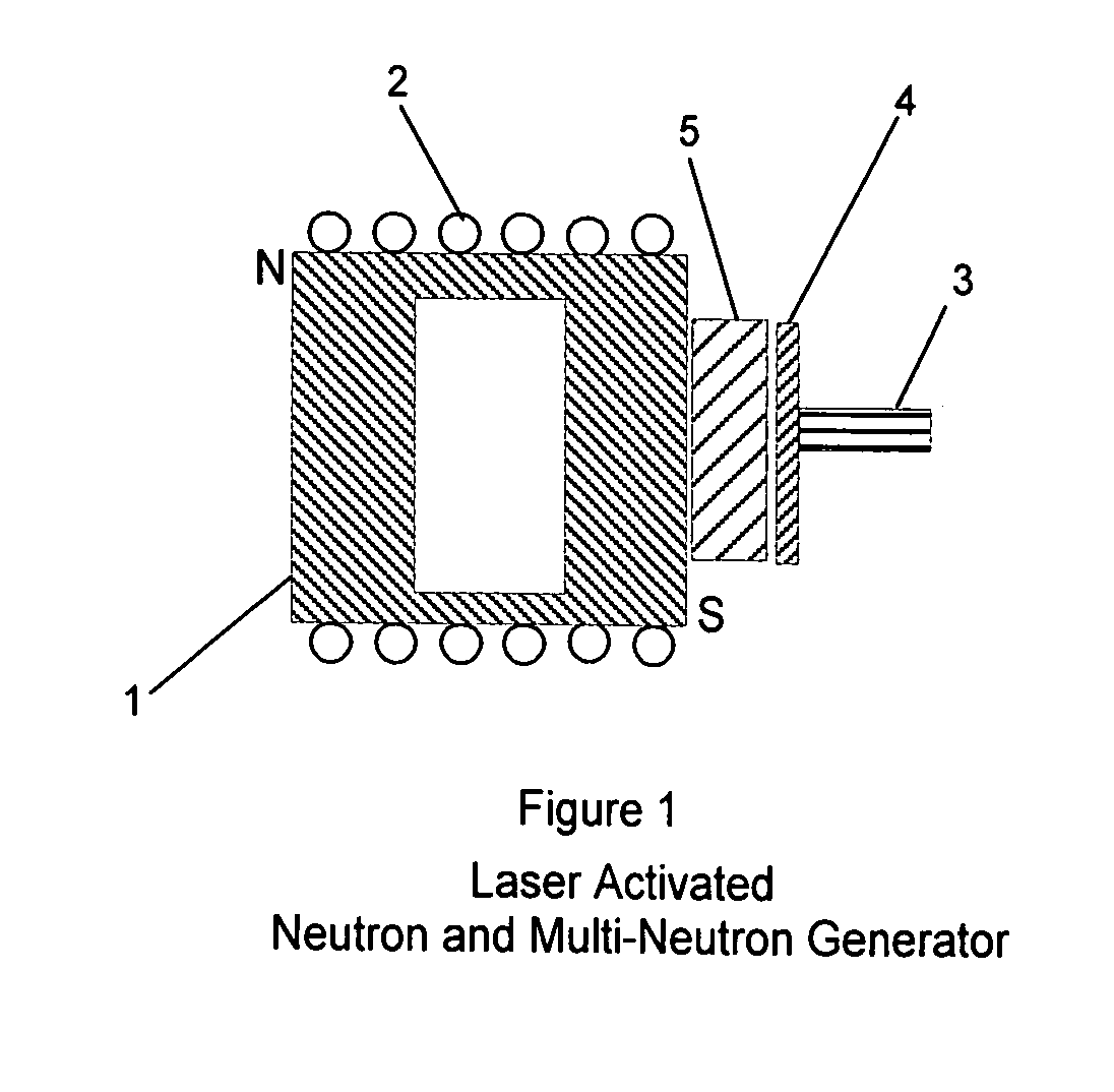
As shown in FIG. 1, there is a specially designed solid iron electrical solenoid 1 with electrical cables 2 wound around the outside surface to provide a magnetic field. To produce starter neutrons incident on solenoid 1, there is an optical laser 3, a layer of photoneutron source material 4, and a neutron moderator 5.

In FIG. 1 the specially configured solid iron electric solenoid 1 provides in itself both north and south magnetic poles that are used respectively, both for anti-polarizing incoming neutrons and for polarizing target neutrons in iron nuclei. Electric cables 2, wound on the exterior of the solid iron solenoid 1, provide electric current to generate the magnetic fields. Optical las...


PUM


Abstract

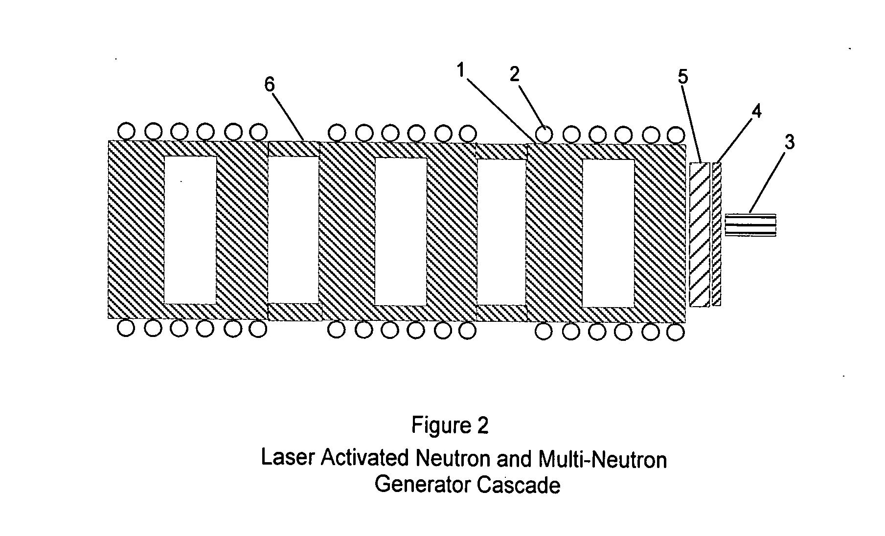
Neutrons and multi-neutron particles are generated in a specially configured solid iron electrical solenoid in which photoneutrons from a metallic strip irradiated by laser photons are selectively polarized and fused together. Nuclear binding energy is released by the nuclear reaction. These neutron generators can be joined in a series so that one feeds neutrons into the next neutron generator to increase the output neutron flux density.

Description

BACKGROUND OF THE INVENTIONThis patent application is subsequent to my Feb. 12, 2009 patent application titled “Solid Iron Solenoid Neutron Initiator for Nuclear Reactor”. The present application utilizes a specially configured electrical solid iron solenoid and an optical laser to produce photoneutrons from a heavy metal target.In November 2006, work was started on the ITER, International Thermonuclear Experimental Reactor located in Cadarche France. This is a version of the Tokamak thermonuclear nuclear fusion reactor invented in the 1950s by Russian scientists and worked on for years at Princeton and Los Alamos. This reactor is expected to produce more heat from nuclear fusion than is required to heat the plasma to fusion temperatures. Deuterium-tritium plasma instability is a major problem, and the ITER nuclear fusion project is expected to last for decades. The ITER thermonuclear fusion process is based on proton-proton fusion reactions. High temperatures and pressures are requ...

Claims


Application Information

Patent Timeline
Patent Type & Authority Applications(United States)
IPC IPC(8): G21B1/00
CPCH05H3/06Y02E30/10
Inventor SCHMIDT, WILLARD H.
Owner SCHMIDT WILLARD H
Why Eureka
Try Eureka