Light guide system, and reflector for controlling out-coupling of light

a technology of light guide and reflector, which is applied in the field of light guide, can solve the problems of emitted light to the wrong side of the light guide, ideal diffuse light source, and loss of light,

Inactive Publication Date: 2011-10-27
TP VISION HLDG
View PDF7 Cites 2 Cited by
  • Summary
  • Abstract
  • Description
  • Claims
  • Application Information

AI Technical Summary

Problems solved by technology

However, a drawback of using LEDs to display ambient light is that each LED may be regarded as a point source.
First of all, these structures, even when mechanically diffuse, do not necessarily result in ideal diffuse light sources with a dominant direction perpendicular to the surface of the light guide.
Furthermore, the diffuse surface emits the light in all directions, i.e. 360 degrees, however with a required perpendicular direction as described above, meaning that some of the light is emitted to the wrong side of the light guide and is lost, unless a mirror is used.
These effects lower the optical efficiency of the ambient light display system.
Finally, the light that couples out from the light guide in the desired direction will not be uniform if a constant structure is applied.
In principle sandblasted dots could be used but these are associated with the same disad...

Method used


Image

  • Light guide system, and reflector for controlling out-coupling of light
  • Light guide system, and reflector for controlling out-coupling of light
  • Light guide system, and reflector for controlling out-coupling of light

Examples


Embodiment Construction

[0029]Several embodiments of the present invention will be described in more detail below with reference to the accompanying drawings in order for those skilled in the art to be able to carry out the invention. The invention may, however, be embodied in many different forms and should not be construed as limited to the embodiments set forth herein. Rather, these embodiments are provided so that this disclosure will be thorough and complete, and will fully convey the scope of the invention to those skilled in the art. The embodiments do not limit the invention, but the invention is only limited by the appended patent claims. Furthermore, the terminology used in the detailed description of the particular embodiments illustrated in the accompanying drawings is not intended to be limiting of the invention.

[0030]The following description focuses on embodiments of the present invention applicable to a light guide system.

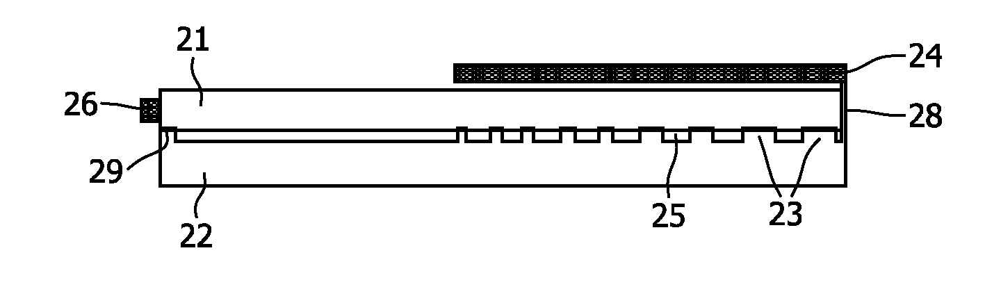
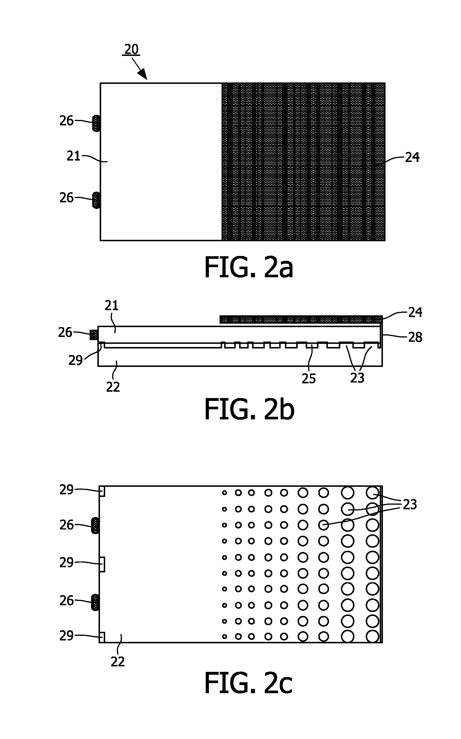
[0031]In an embodiment, according to FIG. 2, a light guide system 20 ...


PUM


Abstract

A light guide system (20) for controlling out-coupling of light is provided. The light guide system comprises a light guide (21) configured to receive ambient light from at least one light source (26), and emit spread ambient light from a surface thereon. The light guide system further comprises a reflector (22) provided with a number of protrusions (23). In use, the reflector (22) and the light guide (21) are attached together. An advantage of this embodiment is that a uniform light -radiating surface using a light guide is enabled.

Description

FIELD OF THE INVENTION[0001]The present invention pertains to the field of light guides, and particularly to a light guide system for enabling uniform out-coupling of light.BACKGROUND OF THE INVENTION[0002]Display systems for enhanced viewing experience when watching video shown on a display device, such as a TV, by using light sources for projecting ambient light are known in the art.[0003]A particularly interesting application is projecting the ambient light towards a viewer.[0004]The benefits of providing ambient light in general includes: a deeper and more immersive viewing experience, improved color, contrast and detail for best picture quality, and reduced eye strain for more relaxed viewing. Different advantages of backlighting require different settings of the backlighting system. Reduced eye strain may require slow changing colors and a more or less fixed brightness while more immersive viewing experience may require an extension of the screen content i.e. the same brightne...

Claims


Application Information

Patent Timeline
IPC IPC(8): F21V7/22
CPCG02B6/0055
Inventor KWISTHOUT, CORNELIS WILHELMUSOVERES, THEODORUS FRANCISCUS EMILIUS MARIANUIJENS, PETRUS GERARDUS JOSEPHUS MARIA
Owner TP VISION HLDG
Why Eureka
Try Eureka