Ultrasonic sensor

a technology of ultrasonic sensor and side wall, applied in the field of ultrasonic sensor, can solve the problems of not only the diaphragm but also the side wall is excited to oscillations of secondary modes, impair the proximity measurement capability of ultrasonic sensor, excitation of secondary modes, etc., to achieve the effect of increasing the improving the reduction of interfering beats, and increasing damping of secondary modes

Active Publication Date: 2011-10-27
ROBERT BOSCH GMBH
View PDF12 Cites 10 Cited by
  • Summary
  • Abstract
  • Description
  • Claims
  • Application Information

AI Technical Summary

Benefits of technology

[0007]As a result of the design of the two side wall sections which are distinguished by the rotationally asymmetrical profile in the lower side wall section which directly surrounds the base surface, and by the transition to a rotationally symmetrical profile at the upper edge of the side wall, the undesired indirect excitation of, for example, secondary oscillation modes as the result of tilting and / or crumpling vibrations of the side walls upon excitation of a main or working oscillation mode of the base surface is significantly reduced by the transducer element in comparison to conventional ultrasonic sensors.
[0009]For ultrasonic sensors which are damped by a foam filling or the like and, depending on the application, optionally incorporated into additional casings which enclose the housing during operation, the characteristic shapes of the individual modes and the increased damping of the secondary modes compared to the working mode may be detected with the aid of laser interferometry. The increased damping of the secondary modes also results in a directly detectable improved reduction in interfering beats in the electrically amplified reception signal of the ultrasonic sensor which compete with the small reflecting ultrasonic signals of nearby objects, thus allowing improved proximity measuring capability of the ultrasonic sensor according to the present invention.
[0010]According to one refinement of the ultrasonic sensor, the side wall in the upper side wall section is at least predominantly tapered with respect to the lower side wall section; i.e., an average wall thickness of the side wall in the upper side wall section is less than in the lower side wall section. According to another refinement, the upper side wall section extends over more than 50% of an overall height of the housing. The upper side wall section may extend over less than 80% of the overall height of the housing. In these refinements the damping of the interfering secondary modes is particularly greatly increased.
[0012]According to one refinement, the side wall has a circumferential outer thickening in the upper side wall section. This thickening acts as a stabilizing ring which results in greater rigidity of the housing, which reduces the occurrence of secondary modes in which the side walls are deflected. In addition, the mechanical robustness of the housing is improved. The outer thickening may extend along the upper edge of the side wall.
[0014]According to another refinement, the upper side wall section includes a curved shape of an inner contour of the housing in a plane perpendicular to the base surface. For a cylindrical or generally rotationally symmetrical outer contour of the housing, for example, the plane perpendicular to the base surface may be a plane which passes through the axis of symmetry of the outer contour, a segment of the intersection line of the inner contour with the plane perpendicular to the base surface forming a curved line. The inner contour may include an essentially quarter-circle-shaped curvature; i.e., a segment of the intersection line of the inner contour with the perpendicular plane extends in the shape of a quarter circle. Particularly advantageous vibration behavior of the housing with particularly high damping of secondary modes may be achieved in these two refinements.

Problems solved by technology

In such designs it is disadvantageous that, in particular in pulsed operation, not only the diaphragm but also the side wall is excited to oscillations of secondary modes.
However, in particular for pulsed transmission excitation of the ultrasonic transducer, this design results in excitation of secondary modes, which typically correspond to tilting and crumpling motions of the diaphragm pot wall.
These secondary modes impair the proximity measuring capability of the ultrasonic sensor, since they prolong the attenuation time after transmission excitation, and beat patterns overlap with small reflected ultrasonic signals from nearby objects.

Method used


Image

  • Ultrasonic sensor
  • Ultrasonic sensor
  • Ultrasonic sensor

Examples


Embodiment Construction

[0025]Unless explicitly stated otherwise, identical or functionally corresponding elements are denoted by the same reference numerals in the figures.

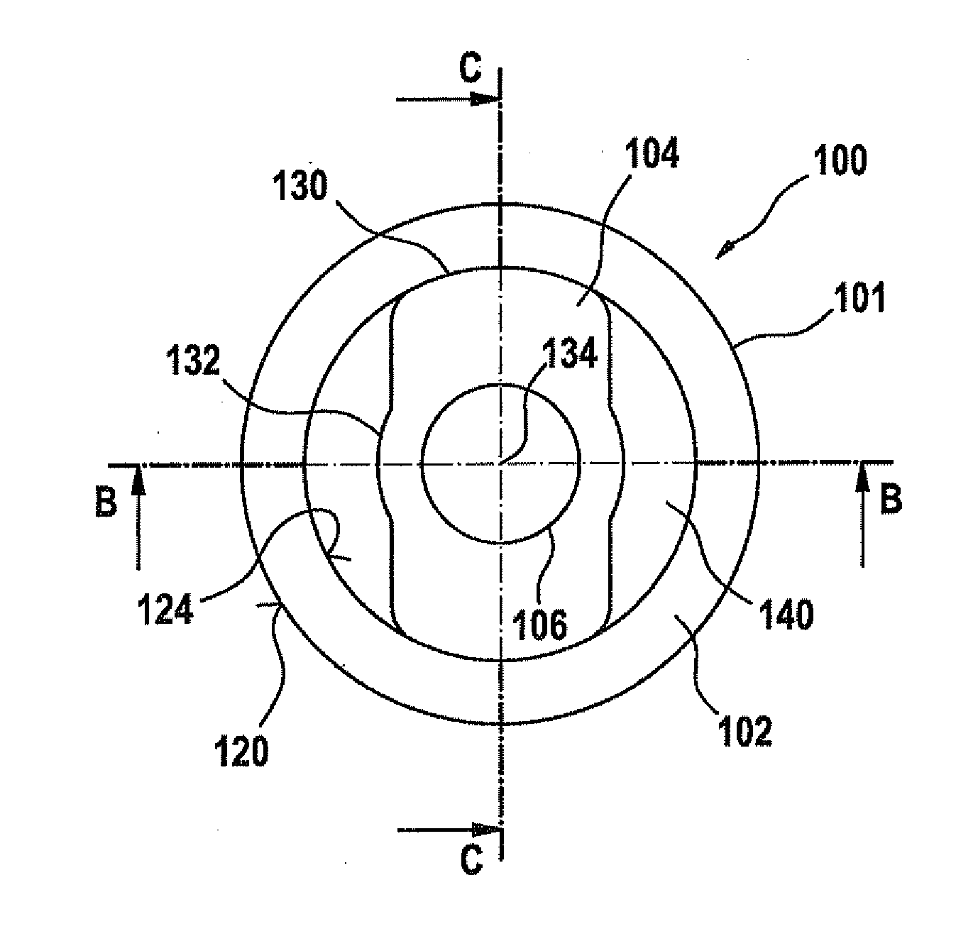
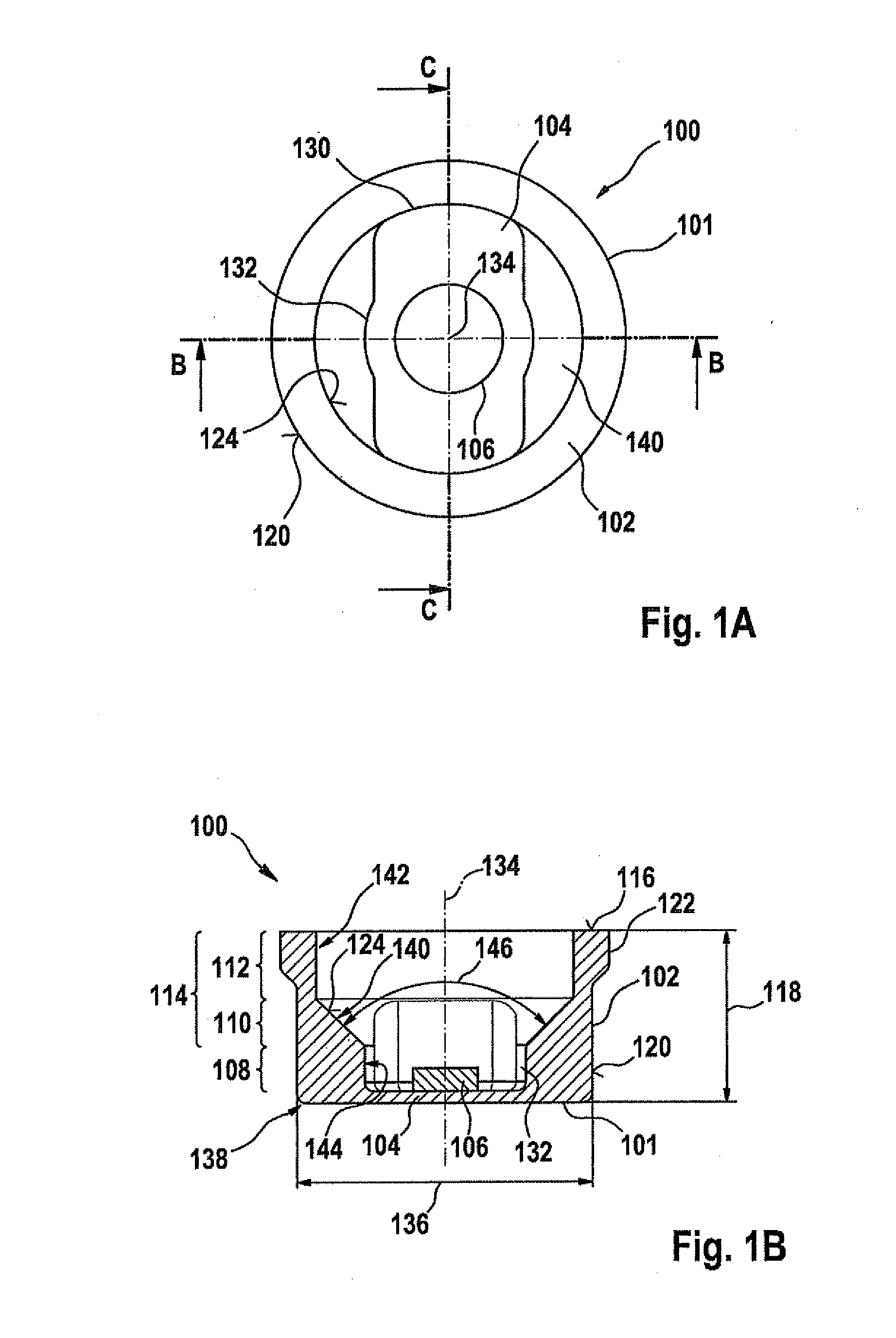
[0026]FIG. 1A shows a top view of an ultrasonic sensor 100 which is suitable for use in a parking assistance system for a motor vehicle. The ultrasonic sensor includes a pot-like housing 101 having a base surface 104 and a side wall 102 which annularly encloses the base surface. Housing 101 is molded or milled from a metallic material such as aluminum, for example, and coated with a primer for purposes of corrosion protection and painting.

[0027]As viewed by the observer, the illustration shows a top view into the interior of housing 101, with the inner side of base surface 104 facing the observer. An electromechanical transducer element 106, in the present case a cylindrical disk-shaped piezoelectric element, for example, is affixed, for example glued, to the inner side of base surface 104 and contacted. The illustration of the contacti...


PUM

PropertyMeasurementUnit
distanceaaaaaaaaaa
aperture angleaaaaaaaaaa

Abstract

An ultrasonic sensor is described having a housing which has a circumferential side wall and a base surface. A transducer element for generating ultrasonic vibrations is mounted on the base surface. The side wall includes a lower side wall section, in which the side wall has an essentially rotationally asymmetrical profile in a plane parallel to the base surface, and an upper side wall section in which the side wall changes to an essentially rotationally symmetrical profile toward an upper edge of the side wall. In other respects, the present system provides a parking assistance system for a vehicle, having a control unit and such an ultrasonic sensor, as well as a method for manufacturing an ultrasonic sensor.

Description

FIELD OF THE INVENTION[0001]The present invention relates to an ultrasonic sensor, a parking assistance system for a vehicle having an ultrasonic sensor, and a corresponding method for manufacturing an ultrasonic sensor.BACKGROUND INFORMATION[0002]Ultrasonic sensors are used in motor vehicles for parking assistance systems, for example, which during parking measure the remaining distance from obstacles bordering a parking space. Such parking assistance systems typically include one or multiple ultrasonic sensors and a control unit, the ultrasonic sensors containing an ultrasonic transducer which is used both for transmitting and receiving ultrasonic signals. In particular, a key functional requirement for the ultrasonic sensors is a so-called proximity measuring capability at a distance range of less than 30 cm.[0003]German patent document DE 3 441 684 A1 discusses an electroacoustic transducer having a cap- or pot-shaped housing whose base surface is designed as a diaphragm. A piez...

Claims


Application Information

Patent Timeline
Patent Type & Authority Applications(United States)
IPC IPC(8): G01N9/04G01R3/00G01S15/931
CPCG01S2015/938G01S15/931Y10T29/49007G10K9/22G01S2015/932G01S7/521
Inventor REICHE, MARTIN
Owner ROBERT BOSCH GMBH
Why Eureka
Try Eureka